
Charging and discharging test system and method

A charging and discharging test, battery technology, applied in the field of testing, can solve the problems of battery mainboard damage, increased cost, battery can not be shared, etc., to achieve the effect of ensuring accuracy, ensuring stability, ensuring stability and accuracy

Active Publication Date: 2017-05-31
UNIVERSAL GLOBAL TECH KUNSHAN
View PDF16 Cites 0 Cited by
  • Summary
  • Abstract
  • Description
  • Claims
  • Application Information

AI Technical Summary

Problems solved by technology

[0004] The traditional method has the following disadvantages: 1) In the process of artificially removing the battery core, if the operation is slightly improper, it will cause damage to the battery motherboard; The firmware (Firmware, FW) burned into the battery in the stage is different, so the battery cannot be shared; 3) Using a fake battery may encounter unstable conditions during the test, for example: some DUTs will change the voltage due to the power supply instantaneously The battery cannot be detected, so that the DUT and the fake battery cannot communicate normally (the information of the fake battery cannot be detected), so that the DUT cannot be successfully charged and discharged.

Method used


Image

  • Charging and discharging test system and method
  • Charging and discharging test system and method
  • Charging and discharging test system and method

Examples


Embodiment Construction

[0033] In order to more clearly illustrate the embodiments of the present invention or the technical solutions in the prior art, the specific implementation manners of the present invention will be described below with reference to the accompanying drawings. Obviously, the accompanying drawings in the following description are only some embodiments of the present invention, and those skilled in the art can obtain other accompanying drawings based on these drawings and obtain other implementations.

[0034] In order to make the drawing concise, each drawing only schematically shows the parts related to the present invention, and they do not represent the actual structure of the product. In addition, to make the drawings concise and easy to understand, in some drawings, only one of the components having the same structure or function is schematically shown, or only one of them is marked. Herein, "a" not only means "only one", but also means "more than one".

[0035] In one emb...


PUM


Abstract

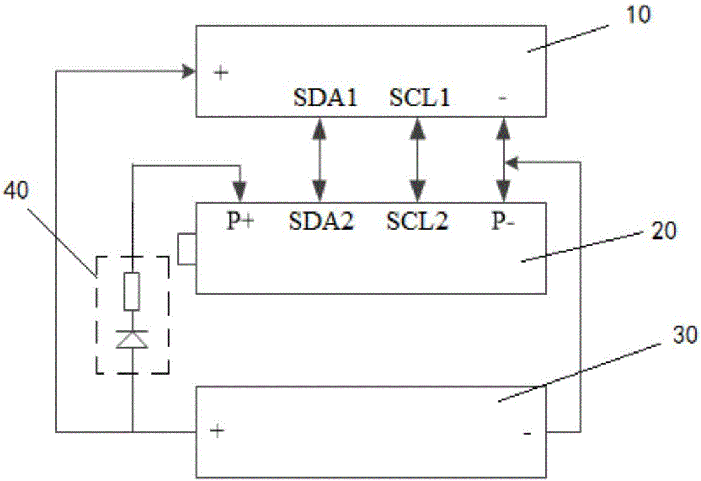
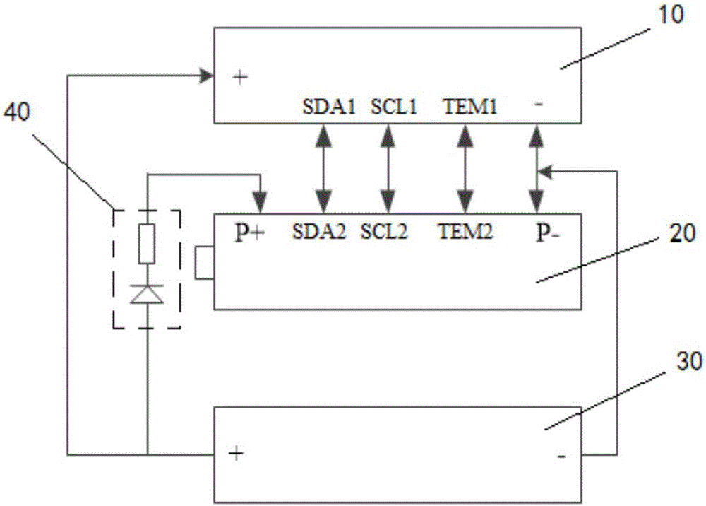
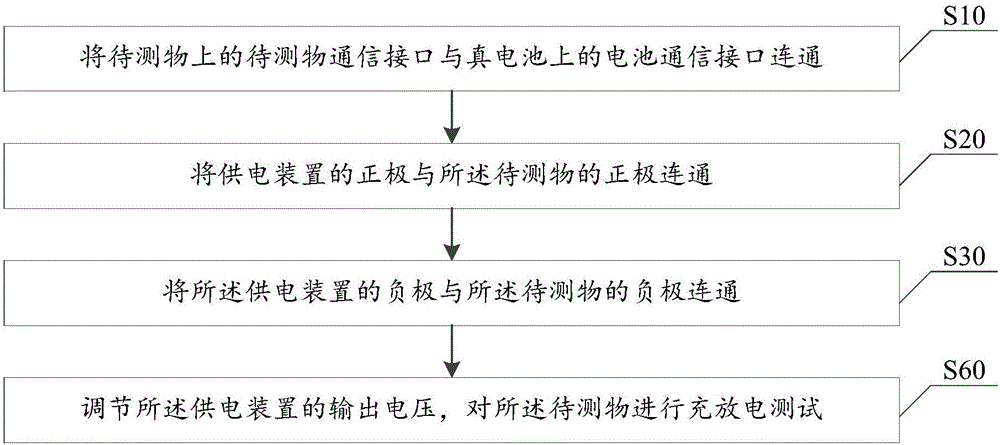
The invention discloses a charging and discharging test system and method. The charging and discharging test system comprises an object to be tested, a true battery and a power supply device, wherein a communication interface of the object to be tested is formed in the object to be tested; a battery communication interface matched with the communication interface of the object to be tested is formed in the true battery; the battery communication interface is electrically connected with the communication interface of the object to be tested; the positive electrode of the power supply device is electrically connected with the positive electrode of the object to be tested; the negative electrode of the power supply device is electrically connected with the negative electrode of the object to be tested. The true battery and the object to be tested are used for performing information interaction; the identical conditions in a practical use process are simulated; the test stability is guaranteed. When the power supply device charges and discharges the object to be tested, the true battery can also be charged, so that the condition that the true battery runs out after being used for a long time cannot occur. In addition, the unilateral conductivity of a diode is utilized, so that the electricity of the true battery cannot flow backwards to the power supply device; the stability and the precision of voltage provided by the power supply device are guaranteed, so that the precision of the charging and discharging test of the object to be tested is guaranteed.

Description

technical field [0001] The invention relates to the field of testing, in particular to a charging and discharging testing system and method. Background technique [0002] With the development of society, various electronic devices have become an indispensable part of people's life, and batteries are an important part of electronic devices. Therefore, for the R&D and testing ends, how to conveniently and quickly verify the charging and discharging functions of electronic products has become a challenge. [0003] When testing the charging and discharging function of the object under test, the traditional method is to use a power supply with variable voltage to connect to the object under test through a dummy battery without a battery cell. Because the real battery cannot change the voltage value immediately during the test, the dummy battery with the battery core removed is used to communicate with the object under test during the test, and the power supply provides voltage t...

Claims


Application Information

Patent Timeline
IPC IPC(8): G01R31/28G01R31/36
CPCG01R31/282G01R31/3644
Inventor 孙艳平郭青峰袁飞腾
Owner UNIVERSAL GLOBAL TECH KUNSHAN
Learn More