
Method for measuring capacitive current of low-current grounding power grid

A technology of small current grounding and capacitive current, which is applied in the direction of capacitance measurement, measuring devices, and measuring electrical variables, etc., can solve problems such as misoperation, dealing with the primary side, and large impedance of the RLC series circuit, so as to achieve accurate measurement and reduce the impact Effect

Inactive Publication Date: 2017-05-31
STATE GRID TIANJIN ELECTRIC POWER +1
View PDF4 Cites 15 Cited by
  • Summary
  • Abstract
  • Description
  • Claims
  • Application Information

AI Technical Summary

Problems solved by technology

The indirect measurement methods that have to deal directly with the primary side, such as the neutral point external capacitance method, are currently used. Although they are simpler than the direct method and can measure the capacitance current value more accurately, they still have the following disadvantages: ①The measurement is still related to Dealing with one side, the safety of personnel and equipment cannot be guaranteed
②Since primary equipment is involved, the operation is cumbersome and there is also the risk of misoperation
[0006] The more commonly used methods in the signal entry method include the three-frequency method and the frequency division method, but the three-frequency method can only be applied to the case where the line-to-ground capacitance is small. When the capacitance is large, the three-frequency method cannot be used anyway. Meet measurement needs
Compared with the three-frequency method, the stability of the frequency division method has been greatly improved, but when measuring a small capacitance, when the frequency of the injected signal is low, the impedance of the entire RLC series circuit will be very large, which is not much different from the excitation impedance of the PT. , in this case, a large measurement error will be caused, so when measuring a small capacitance, the frequency division method will have a large error

Method used


Image

  • Method for measuring capacitive current of low-current grounding power grid
  • Method for measuring capacitive current of low-current grounding power grid
  • Method for measuring capacitive current of low-current grounding power grid

Examples


Embodiment 1

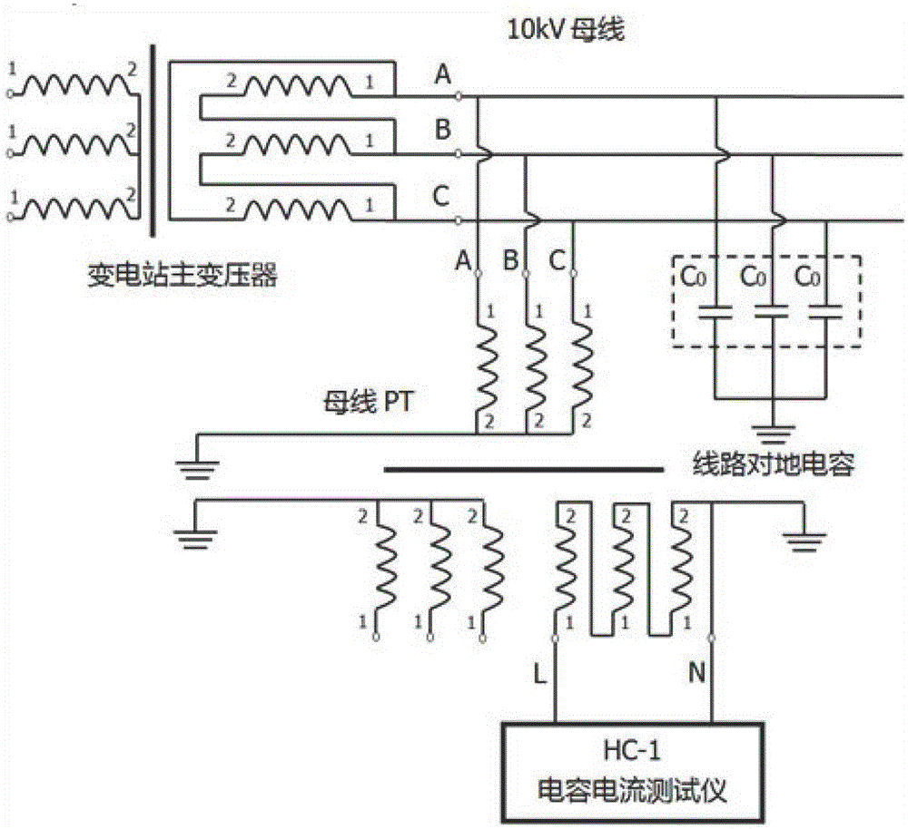
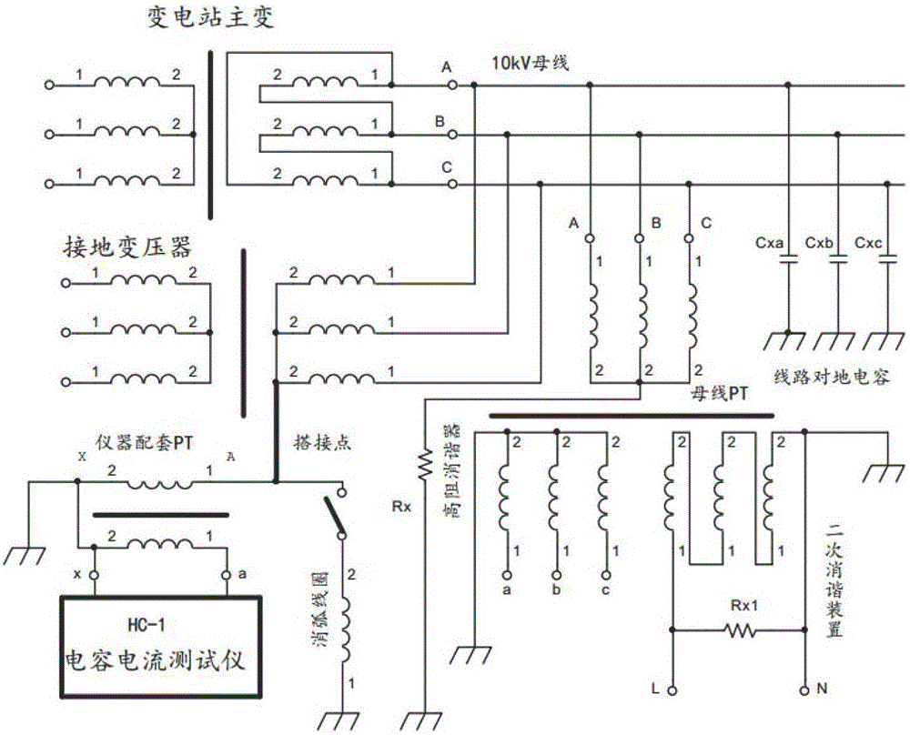
[0052] See figure 2 , a method for measuring the capacitive current of a small-current grounded power grid, using the bus opening triangle PT injection method for measurement, including: HC-1 type capacitive current tester, insulating rod with fuse, grounding transformer, arc suppression coil and bus transformer, in which the bus The low-voltage side of the transformer is connected in a triangle, the arc suppression coil exits, and the HC-1 capacitive current tester injects a 5Hz constant current square wave signal into the low-voltage side of the dedicated PT that is matched with the instrument, and connects the red clip to the a terminal and the black clip to the x terminal The low-voltage side of the PT forms a loop, and the high-voltage side of the PT is connected to the neutral point of the grounding transformer through an insulating rod with a fuse to form a loop with the capacitance of the line to ground. The instrument is equipped with PT low-voltage side voltage and ...


PUM


Abstract

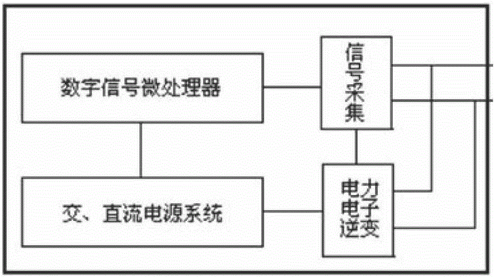
The invention relates to a method for measuring capacitive current of a low-current grounding power grid. The method comprises an HC-1 capacitive current tester and a measurement device, wherein the HC-1 capacitive current tester injects a 5Hz constant-current square wave signal into a zero-sequence circuit of a power distribution network, carries out charging and discharging on a grounding capacitor of a line to measure the grounding capacitive current of the power distribution network; the measurement device comprises an AC / DC power supply system, a digital signal microprocessor, a signal collection unit and a power electronic inverter circuit; the digital signal microprocessor controls the power electronic inverter circuit to generate the 5Hz constant-current square wave signal, and injects the 5Hz constant-current square wave signal into the zero-sequence circuit of the system through a bus open delta of the system, a grounded variable neutral point or a neutral point of a capacitor bank; and a high-performance A / D sampling circuit and digital signal processing are adopted by a signal collection system.

Description

technical field [0001] The invention belongs to the field of power system measurement, in particular to a method for measuring the capacitive current of a small-current grounded power grid. Background technique [0002] In my country, most of the line faults in the medium and low voltage distribution network are single-phase ground faults. Since the neutral point is not grounded, the line voltage vector triangle does not change when the single-phase ground fault occurs, and the neutral point voltage of the three phases remains unchanged. Under the condition that the capacitance current of the power grid is not large and the grounding arc can be self-extinguished, the power grid can continue to supply power for 1 to 2 hours with a fault. Therefore, the early medium and low voltage distribution networks in my country mostly adopted ungrounded methods to improve the reliability and continuity of power supply. With the rapid development of urban construction, more and more cab...

Claims


Application Information

Patent Timeline
Patent Type & Authority Applications(China)
IPC IPC(8): G01R27/26G01R19/25
CPCG01R27/2605G01R19/25
Inventor 仝新宇王永杰李建伟宋兴旺徐笑天陈向东杨乔川沈妍孙明军赵宇王鑫吴杰李晓永李昕王云昊岳洋刘祚安
Owner STATE GRID TIANJIN ELECTRIC POWER
Learn More