
Quantitative measurement method based on integral averaging in pulse infrared heat wave technology

An infrared thermal wave and integral averaging technology, which is applied in measurement devices, material thermal development, material defect testing, etc. The effect of small randomness

Inactive Publication Date: 2017-05-31
CHONGQING NORMAL UNIVERSITY
View PDF8 Cites 9 Cited by
  • Summary
  • Abstract
  • Description
  • Claims
  • Application Information

AI Technical Summary

Problems solved by technology

The possible problem is that the curve fitting parameters have a certain influence on the fitting result, and the fitting result may have a certain error with the real value, especially the first or even second order differential is required on the basis of the curve fitting to obtain The error of the peak time may be larger; the characteristic time is the time corresponding to a certain characteristic value, which only depends on a certain point, and may be greatly affected by noise or the randomness of a single point

Method used


Image

  • Quantitative measurement method based on integral averaging in pulse infrared heat wave technology
  • Quantitative measurement method based on integral averaging in pulse infrared heat wave technology
  • Quantitative measurement method based on integral averaging in pulse infrared heat wave technology

Examples


Embodiment 1

[0127] Embodiment 1. Using reflective pulsed infrared thermal wave technology to measure defect depth

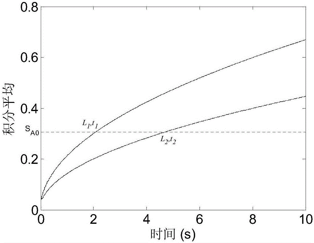
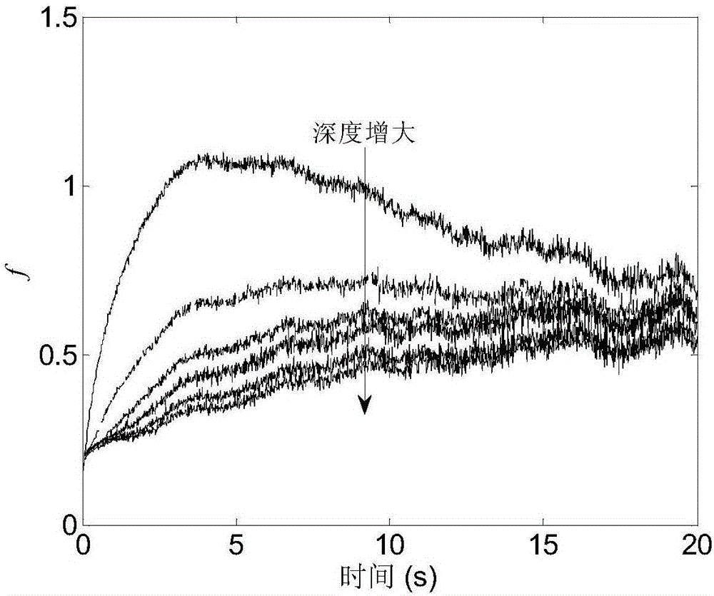
[0128] Using the first stainless steel standard specimen, extract the cooling curve of each flat-bottomed hole center pixel in the heat map of the stainless steel specimen, normalize it with the first frame, and then multiply it by the square root of the corresponding time to obtain a new time series f, such as image 3 shown. The sequence S is obtained by taking the integral average of the sequence f A ,Such as Figure 4 shown. refer to figure 1 , theoretically the integral average curve should be a monotonically increasing sequence, but Figure 4 The second half of the curve corresponding to the middle 1mm hole is monotonously decreasing, which is caused by the small depth of the defect and the obvious three-dimensional thermal diffusion, while the other curves can be regarded as a monotonically increasing sequence within the shown time period. Depend on Figure 4 It...

Embodiment 2

[0129] Embodiment 2. Measuring the thickness of the test piece by the transmission pulse infrared thermal wave technology

[0130] Still using the first stainless steel standard specimen, first obtain the infrared heat map sequence by the transmission experimental scheme, extract the temperature rise curve of each flat-bottomed hole center pixel in the heat map of the stainless steel specimen, and the results are shown in Figure 6 middle. Since the same test piece is used in the transmissive scheme and the reflective scheme in the present invention, the diameter of the flat-bottomed hole is relatively small and the depth of the flat-bottomed hole and the thickness of the test piece have a large difference. There will be certain difficulties, leading to Figure 6 The curves of the two holes of 5-6mm in the center basically have no temperature rise. Therefore, only four holes of 1-4 mm are processed in the following processing. The new time series f is obtained by normalizin...

Embodiment 3

[0131] Embodiment 3. Measuring the thickness of the second layer of the double-layer medium by using the reflective pulsed infrared thermal wave technology

[0132] Using the second standard test piece, one 1.1mm hole is filled with water as a reference hole, and different amounts of water are injected into the other 1.1mm holes for reflective pulsed infrared thermal wave experiments. Extract the cooling curve of the center pixel of the water hole in the heat map of the stainless steel specimen and the corresponding cooling curve of the full water hole as reference curves, and normalize with the first frame. The normalized cooling curve of different water volumes minus the normalized cooling curve of the full water hole is obtained to obtain the thermal contrast curve, and then multiplied by the square root of the corresponding time to obtain the f time series. The sequence S is obtained by taking the integral average of the sequence f A ,Such as Figure 9 shown. choose S ...


PUM


Abstract

The invention relates to a quantitative measurement method based on integral averaging in a pulse infrared heat wave technology. According to the method, a pulse heat source is used for heating reference test pieces made of identical materials; during the reflection type, the heating surface is recorded by a thermal imager, or during the transmission type, the change of the heating back side temperature field is recorded; the original temperature data is subjected to normalization; the processing is performed to obtain an f time sequence; the f sequence is subjected to integral average S value calculation; the corresponding time when the S equals to S<A0> is extracted to be used as the feature time; linear fitting is performed to obtain the slope a and the interception distance b of the feature time and defect depth square relational expression; for the test pieces to be tested, the same experiment scheme, experiment parameters, data processing parameters and the like are used, the feature time t1 is obtained; the defect depth or the test piece thickness is obtained by using the linear formula of the obtained slope a and the interception distance b. The method provided by the invention does not only rely on one point; after interval averaging, the noise influence can be effectively eliminated; the influence by noise is small; the influence by single point randomness is small.

Description

technical field [0001] The invention relates to the technical field of non-destructive flaw detection, in particular to a quantitative measurement method based on integral average in pulsed infrared thermal wave technology. Background technique [0002] Pulse infrared thermal wave non-destructive testing technology is a non-destructive testing technology developed after the 1990s. This method is based on thermal wave theory, by actively applying pulsed thermal excitation to the object to be detected, and using an infrared thermal imager to continuously observe and record the temperature field changes on the surface of the object, and through modern computer technology and image information processing technology for time series Detection, acquisition, data processing and analysis of thermal wave signals to achieve quantitative diagnosis of internal defects or damages. [0003] Pulse infrared thermal wave technology mainly includes two detection methods: reflective and transm...

Claims


Application Information

Patent Timeline
Patent Type & Authority Applications(China)
IPC IPC(8): G01N25/20G01N25/72G01B11/06G01B11/22
CPCG01B11/06G01B11/22G01N25/20G01N25/72
Inventor 曾智
Owner CHONGQING NORMAL UNIVERSITY
Learn More