
Method for measuring weight of railway freight car

A railway freight car and weight measurement technology, which is applied to weighing equipment, special scales, and measuring devices using elastically deformable parts, can solve the problems of low weight measurement accuracy, harsh use environment requirements, and high cost, and achieve measurement results Precise, highly automated, and inexpensive results

Pending Publication Date: 2017-05-31
沈阳风驰软件股份有限公司
View PDF0 Cites 5 Cited by
  • Summary
  • Abstract
  • Description
  • Claims
  • Application Information

AI Technical Summary

Problems solved by technology

[0003] The weight measurement of the contact sensor valve is to adjust the braking force of the empty truck by setting the contact sensor valve above the cross beam or the weight measurement valve at the primary suspension position. The contact sensor valve uses the steering The deflection of the frame spring is used for indirect weight measurement, so the weight measurement accuracy is low, the stability is poor, and the construction is difficult, and the requirements for the use environment are more stringent
[0004] The weight of the railway scale is composed of a load-bearing platform, a load-measuring sensor, and a load-measuring display instrument. Using the four sensors supporting the load-bearing platform, the load of the truck is converted into an electrical signal and amplified by the amplifier, and then converted into a digital signal by the converter and input to the computer. After processing, various data of the truck load can be displayed, and records can be printed; this measurement method is affected by the front and rear compartments, the measurement value is unstable, and it occupies a large area, the construction is difficult, and it is not easy to maintain
[0005] Existing weighing methods cannot measure accurately and the operation of measuring equipment is cumbersome and costly

Method used


Image

  • Method for measuring weight of railway freight car
  • Method for measuring weight of railway freight car
  • Method for measuring weight of railway freight car

Examples


Embodiment Construction

[0027] The present invention will be described in further detail below in conjunction with the accompanying drawings.

[0028] Such as Figure 1 to Figure 2 as shown in

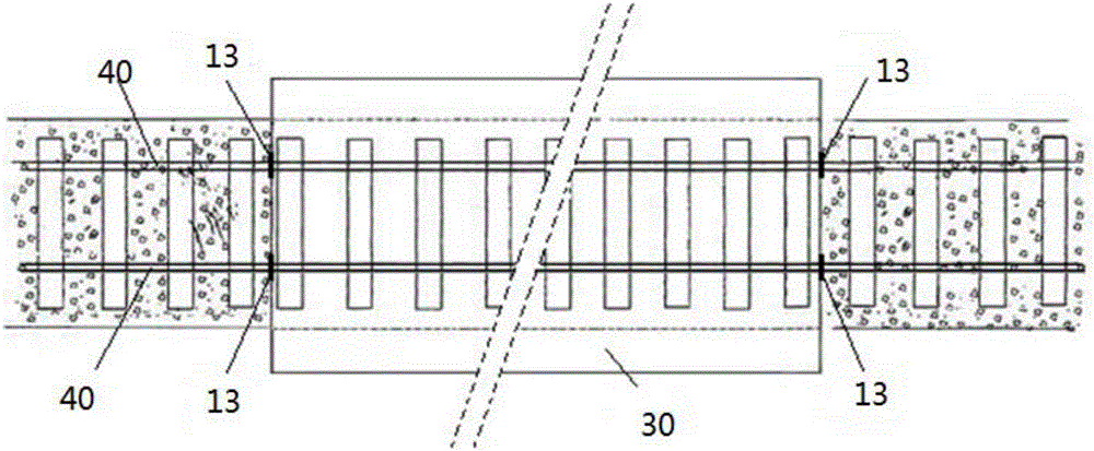
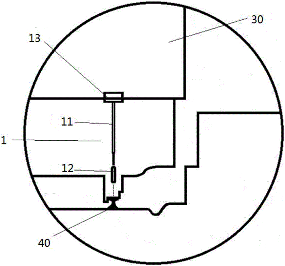
[0029] According to the method for weight measurement of railway freight cars of the present invention, a single truck carriage 30 is used as a unit to realize the method of weight measurement, and four sensor supports 10 and lasers respectively installed on the sensor support 10 are arranged at the bottom of the single carriage. The distance measuring sensor 20; the sensor support member 10 includes the sensor support rod main rod part 11, the laser ranging sensor fixing part 12 installed on one end of the sensor support rod main rod part 11 by welding or bolting or integrally formed and installed on the sensor support rod The ground vertical alignment mechanism 13 at the other end of the main rod portion 11 is fixed on the front and rear corners of the truck compartment 30 directly above the rail 40 by han...


PUM


Abstract

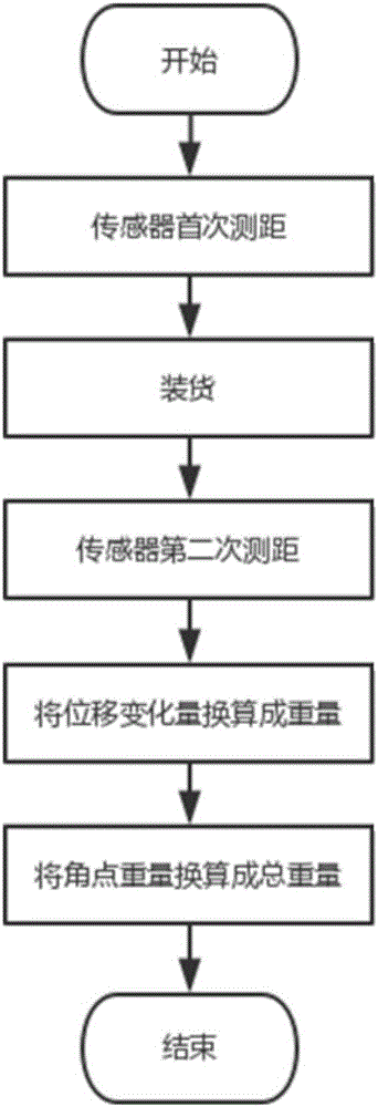
The invention discloses a method for measuring the weight of a railway freight car. A single boxcar serves as a unit, and the method for measuring the weight of the railway freight car is achieved. The bottom of the single boxcar is provided with four sensor supporting parts and laser ranging sensors which are installed on the sensor supporting parts respectively. The method includes the steps that firstly, the four laser ranging sensors conduct first-time ranging before the boxcar is loaded, and after the boxcar is loaded, the four laser ranging sensors conduct second-time ranging; then, the displacement variable quantity of the four laser ranging sensors during two-time ranging is converted into weight; finally, by moment equilibrium calculation, the weight of the carry freight of the single boxcar is obtained. The method for measuring the weight of the railway freight car is convenient to operate and low in cost, and can not only conveniently and rapidly measure the weight of a tested object, but also be higher in automation degree and accurate in measuring result and meet weight measuring requirements of various occasions.

Description

technical field [0001] The invention relates to the technical field of railway freight car weight measurement, in particular to a method for railway freight car weight measurement. Background technique [0002] There has never been a simple and accurate way to measure the weight of railway wagons. Now there are two commonly used measurement methods: contact sensor valve weight measurement and railway scale weight measurement. [0003] The weight measurement of the contact sensor valve is to adjust the braking force of the empty vehicle by setting the contact sensor valve above the cross beam or the weight measurement valve at the primary suspension position. The contact sensor valve uses the steering The frame spring deflection is used for indirect weight measurement, so the weight measurement accuracy is low, the stability is poor, and the construction is difficult, and the requirements for the use environment are relatively strict. [0004] The weight of the railway scale...

Claims


Application Information

Patent Timeline
Patent Type & Authority Applications(China)
IPC IPC(8): G01G19/08G01G3/12
CPCG01G19/08G01G3/125
Inventor 牛冬校周文华
Owner 沈阳风驰软件股份有限公司
Learn More