
Bulletproof composite board and preparation method thereof

A composite material layer and plate technology, which is applied in the field of composite bulletproof plate and its preparation, can solve the problems of poor understanding of protection mechanism and performance interface combination, and achieve the effects of improving anti-fragmentation performance, excellent bulletproof performance, and reducing the depth of craters

Inactive Publication Date: 2017-05-31
江苏安卡新材料科技有限公司
View PDF5 Cites 10 Cited by
  • Summary
  • Abstract
  • Description
  • Claims
  • Application Information

AI Technical Summary

Problems solved by technology

However, since metal and non-metal materials are in different fields, they do not have a deep understanding of the protection mechanism, performance and interface combination of each other. Therefore, metal and non-metal composite bulletproof materials are still rarely studied in China.

Method used


Image

  • Bulletproof composite board and preparation method thereof

Examples


Embodiment 1

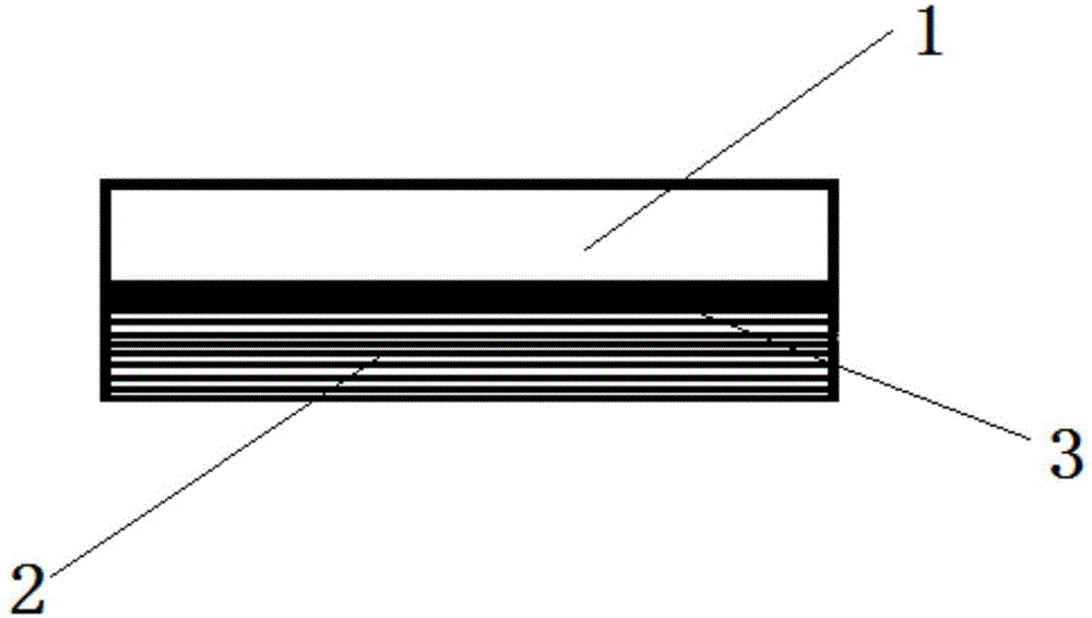
[0022] see figure 1 As shown, a composite bulletproof plate includes a bulletproof surface 1, an interface 3 and a backing surface 2, the bulletproof surface 1 is a bulletproof metal material layer, specifically a bulletproof steel plate; the backing surface 2 is a high-performance fiber Composite material layer, the bulletproof steel plate and the high-performance fiber composite material layer are glued through the interface 3; the thickness of the bulletproof steel plate is 2.2mm, the hardness value (HB) is 500-550, and the ultra-high performance fiber composite material The thickness of the layer is 12mm, which is specifically composed of 90 layers of ultra-high molecular weight polyethylene non-woven fabric laminates and 1 layer of aramid non-woven fabric laminates. The interface 3 is a styrene-based block copolymer elastomer.

[0023] The above-mentioned preparation method of a composite bulletproof plate comprises the steps of:

[0024] (1) Preparation of bulletproof m...

Embodiment 2

[0028] see figure 1 As shown, a composite bulletproof plate includes a bulletproof surface 1, an interface 3 and a backing surface 2, the bulletproof surface 1 is a bulletproof metal material layer, specifically a bulletproof steel plate; the backing surface 2 is a high-performance fiber Composite material layer, the bulletproof steel plate and the high-performance fiber composite material layer are glued together through the interface 3; the thickness of the bulletproof steel plate is 2.3 mm, the hardness value (HB) is 550-600, and the thickness of the high-performance fiber composite material layer is It is 14mm, and it is specifically formed by hot pressing of 105 layers of ultra-high molecular weight polyethylene non-weft laminated boards, and the interface 3 is a TPU hot-melt adhesive film.

[0029] The above-mentioned preparation method of a composite bulletproof plate comprises the steps of:

[0030] (1) Preparation of bulletproof metal material layer on the bulletproo...


PUM

PropertyMeasurementUnit
Thicknessaaaaaaaaaa
Thicknessaaaaaaaaaa
Thicknessaaaaaaaaaa

Abstract

The invention discloses a bulletproof composite board and a preparation method thereof. The bulletproof composite board comprises a bullet-ward face, an interface and a backing face, wherein the bullet-ward face is a bulletproof metal material layer, the backing face is a high-performance fiber composite material layer, and the bulletproof metal material layer and the high-performance fiber composite material layer are glued together through the interface. The bulletproof metal material layer is made of a bulletproof metal plate or a bulletproof titanium alloy material. The high-performance fiber composite material layer is selectively formed by laminating one or more layers made of one or more of an ultra high molecular weight polyethylene non-woven cloth laminated board, an aramid fiber non-woven cloth laminated board and an aramid fiber woven cloth laminated board. The finished bulletproof composite board has excellent bulletproof performance, and compared with metal boards on the same bulletproof level, the weight of the bulletproof composite board is reduced by 30% or over, and meanwhile, breakage resistance is improved; and compared with high-performance fiber composite boards, the cost is reduced by about 50%, and meanwhile, the depths of bullet pits are decreased.

Description

technical field [0001] The invention relates to the field of bulletproof materials, in particular to a composite bulletproof plate and a preparation method thereof. Background technique [0002] At present, the main bulletproof panels are divided into two types: metallic materials and non-metallic materials. [0003] Bulletproof plates made of metal materials are mainly high-strength bulletproof grade steel plates or bulletproof grade titanium alloy plates. Relying on their own high hardness and certain toughness, they can destroy the bullet structure and bullet core and prevent bullets from penetrating. The price is relatively low, but the weight is large and the impact is dispersed. If the energy is not good, it is easy to cause secondary damage. [0004] Non-metallic bulletproof panels are mainly high-strength fiber laminates, relying on the fabric structure to transmit impact energy as soon as possible, while the fracture and deformation of high-strength fibers absorb i...

Claims


Application Information

Patent Timeline
IPC IPC(8): F41H5/04B32B15/14B32B15/18B32B27/02B32B27/12B32B27/32B32B27/34B32B37/12B32B37/06B32B37/10B32B7/12
CPCF41H5/0485B32B5/12B32B5/26B32B7/12B32B15/14B32B15/18B32B37/06B32B37/10B32B37/12B32B37/1207B32B2037/1223B32B2037/243B32B2255/06B32B2255/26B32B2262/0253B32B2262/0269B32B2307/718B32B2309/02B32B2309/04B32B2309/12B32B2311/30B32B2323/04B32B2377/00B32B2571/02
Inventor 徐永红李振国丁旭张苏宁
Owner 江苏安卡新材料科技有限公司
Learn More