
Dew point temperature controlling method and device

A technology of dew point temperature and control method, which is applied in heating and ventilation control system, control input related to air characteristics, space heating and ventilation control input, etc. It can solve problems such as inability to realize refrigeration, increase use cost, and failure of air conditioning system , to achieve the effect of preventing condensation in the capillary network

Inactive Publication Date: 2017-05-31
HAILIN ENERGY TECH
View PDF6 Cites 23 Cited by
  • Summary
  • Abstract
  • Description
  • Claims
  • Application Information

AI Technical Summary

Problems solved by technology

[0004] In the prior art, a dew point thermostat is usually used to control the anti-condensation temperature, and a dehumidification controller is used to control the indoor humidity. When the dew point thermostat detects that there is a risk of condensation, the water system will be closed, but this control The solution has the following disadvantages: in the high temperature and high humidity environment in summer, the dew condensation temperature will be close to the room temperature, and the water system will be forced to shut down, which will cause the air conditioning system to fail and cooling cannot be realized; moreover, the use of multiple controllers will undoubtedly increase the cost of use, cause waste

Method used


Image

  • Dew point temperature controlling method and device
  • Dew point temperature controlling method and device
  • Dew point temperature controlling method and device

Examples


Embodiment Construction

[0049] In order to enable those skilled in the art to better understand the solutions of the embodiments of the present invention, the embodiments of the present invention will be further described in detail below in conjunction with the drawings and implementations.

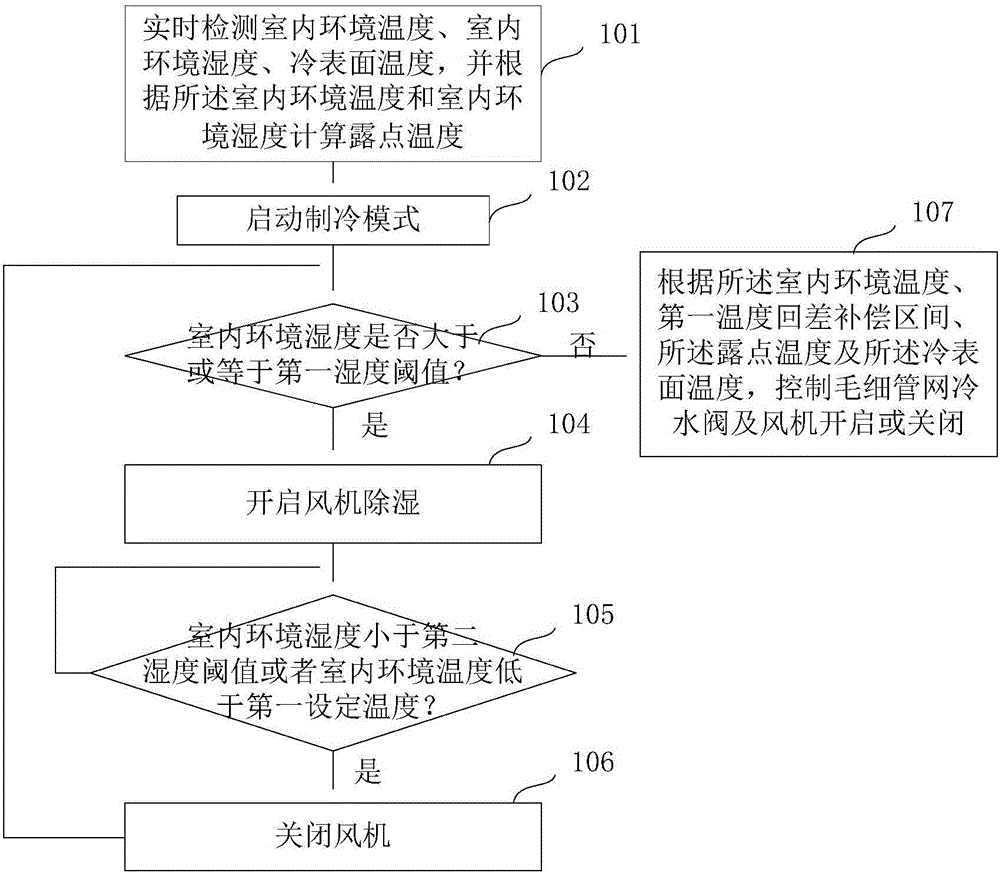
[0050] Such as figure 1 Shown is a flow chart of the dew point temperature control method of the present invention in refrigeration mode, including the following steps:

[0051] Step 101, real-time detection of indoor ambient temperature, indoor ambient humidity, and cold surface temperature, and calculating dew point temperature according to the indoor ambient temperature and indoor ambient humidity.

[0052] The indoor ambient temperature, indoor ambient humidity, and cold surface temperature can be obtained specifically through corresponding sensors, and the cold surface temperature refers to the ambient temperature outside the capillary network.

[0053] The dew point temperature refers to the temperature w...


PUM


Abstract

The invention discloses a dew point temperature controlling method and device. The method comprises the following steps that the indoor environment temperature, the indoor environment humidity and the cold surface temperature are detected in real time, and the dew point temperature is calculated according to the indoor environment temperature and the indoor environment humidity; under a refrigerating mode, if the indoor environment humidity is larger than or equal to a first humidity threshold, a fan is only started to conduct dehumidification till the indoor environment humidity is smaller than a second humidity threshold or the indoor environment temperature is lower than a first set temperature, the fan is closed, wherein the second humidity threshold is smaller than the first humidity threshold; and if the indoor environment humidity is smaller than the first humidity threshold, a capillary network cold water valve and the fan are controlled to be started or closed according to the indoor environment temperature, a first temperature return difference compensating section, the dew point temperature and the cold surface temperature, so that the indoor environment temperature is adjusted to be maintained within the first temperature return difference compensating section. By means of the dew point temperature controlling method, unified control over a refrigerating system and a dehumidifying system can be achieved, the dew formation of a capillary network is effectively avoided, and the refrigerating requirement under a high-temperature and high-humidity environment is not affected.

Description

technical field [0001] The invention relates to the technical field of temperature controllers, in particular to a dew point temperature control method and device. Background technique [0002] Today's air conditioning systems in modern buildings have to meet high demands. Traditional air conditioning systems such as ventilation and static heating are difficult to simultaneously achieve the best thermal comfort, the most space-saving and energy-saving requirements. Capillary is a new technology in this field, which can automatically adjust to the surrounding environment. The capillary network generally uses water as the medium to transport energy, which is characterized by high efficiency, energy saving and high comfort. The capillary network can be combined with the decorative layer and installed on the ceiling, floor or wall to evenly distribute energy, so that the energy transfer between the user and the room surface is carried out by radiation. [0003] The solution t...

Claims


Application Information

Patent Timeline
Patent Type & Authority Applications(China)
IPC IPC(8): F24F11/00
CPCF24F2110/20F24F11/30F24F11/62F24F11/65F24F11/83F24F11/84F24F2110/10
Inventor 刘琳
Owner HAILIN ENERGY TECH
Learn More