Shell-and-tube heat exchanger of heat recovery boiler

A technology of tube-and-tube heat exchangers and waste heat boilers, applied in the field of waste heat boilers, can solve the problems of large dust content in boiler flue gas, accumulated smoke and dust, and reduced heat transfer efficiency, and achieve the effect of improving recovery efficiency and high heat transfer efficiency

Inactive Publication Date: 2017-05-31
JIANGSU HUAYUE SPECIAL EQUIP
View PDF0 Cites 0 Cited by
  • Summary
  • Abstract
  • Description
  • Claims
  • Application Information

AI Technical Summary

Problems solved by technology

[0003] The purpose of the present invention is to provide a waste heat boiler tube heat exchanger to solve the problem that the existing boiler flue gas used in iron and steel enterprises has a large dust content. When using a water tube waste heat boiler, the heat exchange tube wall will accumulate Smoke and dust, leading to technical problems that reduce heat transfer efficiency

Method used


Image

  • Shell-and-tube heat exchanger of heat recovery boiler

Examples


Embodiment Construction

[0011] The present invention is described in further detail now in conjunction with accompanying drawing. These drawings are all simplified schematic diagrams, which only illustrate the basic structure of the present invention in a schematic manner, so they only show the configurations related to the present invention.

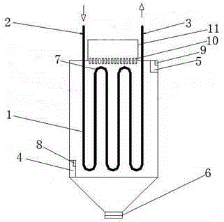
[0012] Such as figure 1 As shown, a waste heat boiler tube heat exchanger includes: heat exchange tubes are vertically arranged in the heat exchanger, and the two ends of the heat exchange tubes are respectively a water inlet 2 and a water outlet 3 , the water inlet 2 and the water outlet 3 are all arranged on the top of the heat exchanger, the left lower end of the heat exchanger is provided with an air inlet 4, and the right upper end of the heat exchanger is provided with an air outlet 5, and The bottom of the heat exchanger is provided with a receiving port 6; wherein the heat exchange tubes include several U-shaped heat exchange tubes 1, and several U-sh...


PUM


Abstract

The invention relates to a shell-and-tube heat exchanger of a heat recovery boiler. A heat exchange nest of tubes is vertically arranged inside the heat exchanger. A water inlet and a water outlet are formed in the two ends of the heat exchange nest of tubes correspondingly. Both the water inlet and the water outlet are formed in the top of the heat exchanger. An air inlet is formed in the lower end of the left side of the heat exchanger. An air outlet is formed in the upper end of the right side of the heat exchanger, and a containing opening is formed in the bottom of the heat exchanger. A high-pressure water tank is arranged at the top of the heat exchanger. A plurality of water spraying holes are formed in the connecting position of the high-pressure water tank and the heat exchanger. Due to arrangement of the high-pressure water tank at the top of the heat exchanger, water in the high-pressure water tank can wash soot on the tube walls of the heat exchange nest of tubes through the water spraying holes, high heat exchange efficiency can be kept continuously, waste heat recovery is fully conducted, and the recovery benefits of a waste heat system are increased.

Description

technical field [0001] The invention relates to a waste heat boiler, in particular to a tube-and-tube heat exchanger for the waste heat boiler. Background technique [0002] During the use of boilers in iron and steel enterprises, a large amount of fuel is usually consumed, accompanied by a large amount of flue gas, and the exhaust gas temperature of the boilers used in iron and steel enterprises is also very high. In the past, these high-temperature flue gases were directly discharged to the atmosphere , resulting in a huge waste of resources. At present, in order to save energy, many technologies have been produced to recover the waste heat of this high-temperature flue gas. In the existing technology, the waste heat recovery and utilization facilities usually used are heat exchangers, which are A device that can not only reduce the temperature of flue gas, but also utilize high-temperature flue gas to achieve the purpose of heat exchange. However, due to the drastic temp...

Claims


Application Information

Patent Timeline
Patent Type & Authority Applications(China)
IPC IPC(8): F23J15/06F23J3/02
CPCF23J3/02F23J15/06Y02E20/30
Inventor 朱正虎
Owner JIANGSU HUAYUE SPECIAL EQUIP
Why Eureka
Try Eureka