
Tempering control device for cutting torch

A control device and cutting torch technology, which is applied in the direction of burner safety device, gas fuel burner, combustion method, etc., can solve the problems of unfamiliar switch direction of the knob switch, long closing cycle, leather tube burn, etc., to avoid safe production Accident, easy installation, simple structure effect

Inactive Publication Date: 2017-05-31
ZHENJIANG WATERCRAFT COLLEGE OF PLA
View PDF4 Cites 0 Cited by
  • Summary
  • Abstract
  • Description
  • Claims
  • Application Information

AI Technical Summary

Problems solved by technology

At present, the backfire prevention device on the gas cutting equipment is mainly to install a one-way valve on the gas pipe to prevent the flame from flowing back into the gas cylinder. Although this effectively prevents the flame from flowing back into the acetylene cylinder and causing an explosion, it does not prevent the backfire from burning out. Insignificant role of accidents involving cutting torches, leather hoses, and burns to welders
The original knob switch on the cutting torch has a long closing cycle after the tempering occurs, and beginners are not familiar with the switching direction of the knob switch, and it is easy to cause accidents such as burning the torch, leather tube and burn welder because the valve is not closed in time occur

Method used


Image

  • Tempering control device for cutting torch
  • Tempering control device for cutting torch

Examples


Embodiment Construction

[0017] The following will clearly and completely describe the technical solutions in the embodiments of the present invention with reference to the drawings in the embodiments of the present invention.

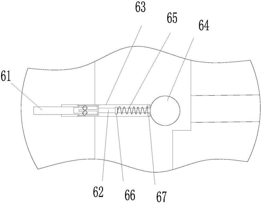
[0018] figure 1 and 2 As shown, a cutting torch tempering control device 6 is arranged in the cutting torch to realize explosion-proof, including a mixed oxygen switch 1, an acetylene gas switch 2, a high-pressure oxygen switch 3, a high-pressure oxygen tube 4, an acetylene gas tube 7 and oxyacetylene The mixing tube 5, the tempering control device 6 is arranged at the junction of the high-pressure oxygen tube 4 and the oxyacetylene mixing tube 5, which includes a fixing seat 63, and the fixing seat 63 is provided with a first push rod 61 and a second Two push rods 62, the end of the second push rod 62 is provided with a ball valve 64, pushes the first push rod 61, and the second push rod 62 can drive the ball valve 64 to move so that the ball valve 64 will The acetylene gas...


PUM


Abstract

The invention discloses a tempering control device for a cutting torch. The tempering control device is arranged in the cutting torch and is used for preventing explosion. The tempering control device comprises a mixed oxygen switch, an acetylene gas switch, a high pressure oxygen switch, a high pressure oxygen pipe, an acetylene gas pipe and an oxyacetylene mixing pipe, wherein the tempering control device is arranged at a joint of the high pressure oxygen pipe and the oxyacetylene mixing pipe; the tempering control device comprises a fixing base; a first push rod and a second push rod are arranged in the fixing base; a ball valve is arranged on an end part of the second push rod; and when the first push rod is pushed, the second push rod can drive the ball valve to move so as to seal the acetylene gas pipe by the ball valve. After the tempering control device for the cutting torch, provided by the invention, is arranged on the cutting torch, the one-key control of tempering of the cutting torch can be realized, and a series of safety production accidents caused by improper treatment or delayed treatment can be avoided. The device adopts button type manual control, the structure is simple, safe and reliable, the tempering control device is easily mounted, and the cutting torque is not greatly modified.

Description

technical field [0001] The invention specifically relates to a cutting torch tempering control device. [0002] Background technique. [0003] The ejector-suction cutting torch has the advantages of simple structure and light equipment, which is convenient for field operations. The operation method is flexible and convenient. It can cut the section shape and thickness that are difficult to cut by mechanical methods, and it is economical. It is indispensable in the industrial production process. A cutting tool. However, in the process of gas cutting, due to various complex reasons such as cutting nozzle blockage, air leakage, cutting nozzle being too close to the workpiece, and high temperature, the speed of oxyacetylene mixed gas flowing out of the cutting nozzle is lower than the combustion speed of the mixed gas, resulting in reverse combustion of the flame. If the flame flows back and burns out the cutting torch, leather tube, burns the welder or even enters the acetylene...

Claims


Application Information

Patent Timeline
Patent Type & Authority Applications(China)
IPC IPC(8): F23D14/42F23D14/46F23D14/82
CPCF23D14/42F23D14/465F23D14/825F23D2209/10F23D2900/14381
Inventor 姜士阳崔宇峰宁海强
Owner ZHENJIANG WATERCRAFT COLLEGE OF PLA
Learn More