Quakeproof pole tower

A technology of anti-vibration rods and rod bodies, applied in towers, building types, buildings, etc., can solve problems such as uneven settlement, easy breaking, and grid damage, so as to improve structural stability and reliability, and reduce deflection or hard damage , Strong cushioning and shock-absorbing ability

Inactive Publication Date: 2017-05-31
STATE GRID HENAN ELECTRIC ZHOUKOU POWER SUPPLY
View PDF12 Cites 6 Cited by
  • Summary
  • Abstract
  • Description
  • Claims
  • Application Information

AI Technical Summary

Problems solved by technology

[0002] At present, the tower design and structural safety and stability construction of 35KV and below power transmission and distribution lines in the power grid are relatively weak. The towers for power transmission and wiring are all equipped with thick cylinders at the bottom, with brackets at the top, and tree-like shapes at high altitude. It is suitable for erecting wires and cables, the bottom of which is connected by bolts to the foundation that is simply laid underground. However, this traditional rigid fixing method between the tower and the ground is difficult to resist the vibration of the foundation or the occurrence of earthquake disasters. When an earthquake occurs, the foundation is often cracked and damaged. Uneven settlement, etc.; when natural disasters such as strong winds, heavy snow, heavy rain, and ice cover occur, the tower will be tilted and overturned like a "domino" effect. Power outages seriously endanger the safety of electricity and the electricity consumption of residents in production and life, and bring immeasurable losses to the national economy.
On August 14, 2013, a tornado hit Pushi Town, Luxi County, Xiangxi Autonomous Prefecture. After the tornado, the roofs of Neiwa houses in the town were overturned, and the utility poles collapsed in rows and fell on the roofs of residents or trees. More than 5 The 10 kV line was affected by the disaster, affecting nearly 100,000 residents in four villages and towns for production and living electricity. However, the current common method is to prefabricate concrete at the base, and then connect the bottom of the pole through the flange. If the concrete base is small It is easy to settle, and if it is very large, it will waste a lot of resources, and the flange connection method is easy to break under conditions such as strong winds and vibrations, and there are still major safety hazards. Therefore, how to design a new type of tower structure to make the disaster-resistant ability greatly improved
The disadvantage of this structure is that the connection between the pole and the base is still rigid, and the earthquake resistance is not strong in the face of the shear wave and longitudinal wave of the earthquake
The disadvantage of this structure is: the structure is complicated, and the installation process is time-consuming and laborious

Method used


Image

  • Quakeproof pole tower
  • Quakeproof pole tower
  • Quakeproof pole tower

Examples


Embodiment 1

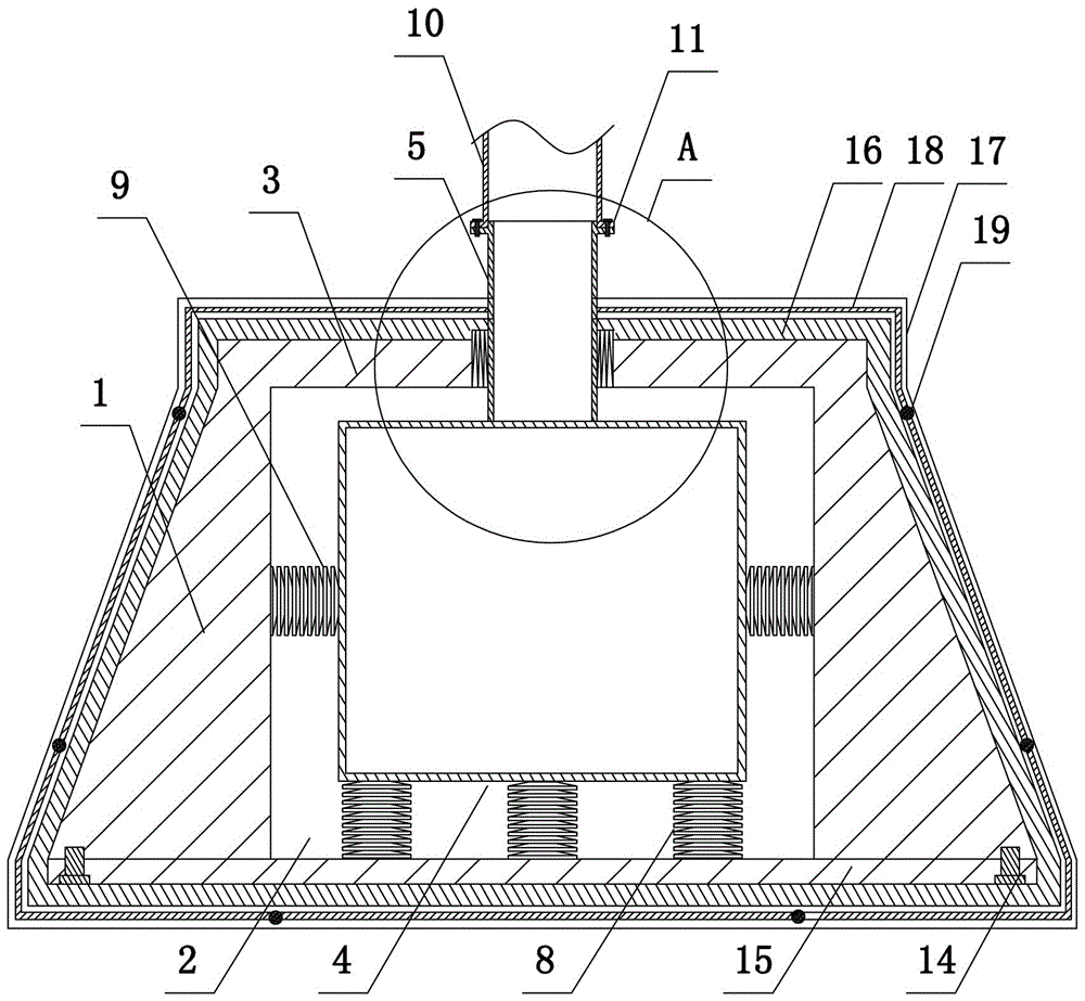
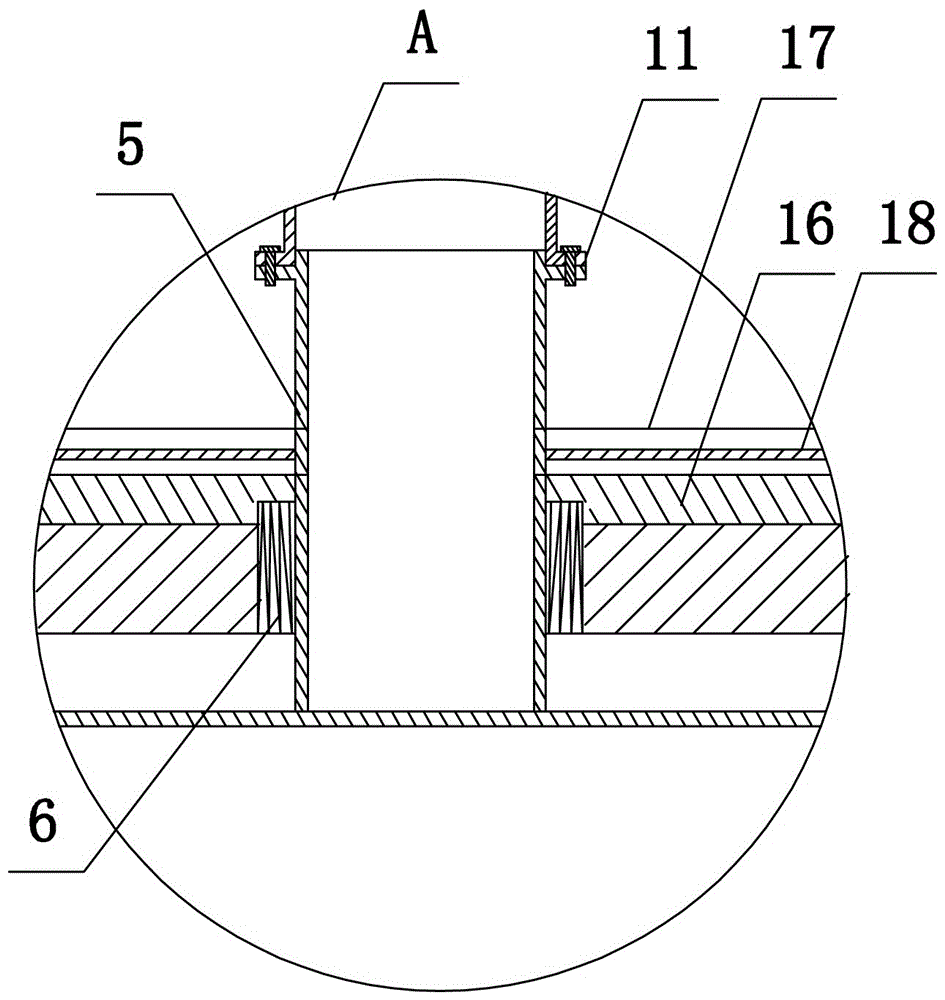
[0027] like figure 1 and figure 2 As shown, the present invention includes a rod body 10, a moisture-proof casing and a shockproof mechanism arranged in the moisture-proof casing. The moisture-proof casing includes a symmetrically arranged front casing (not shown), a rear casing 16, and the front casing and the rear casing 16 are integrally formed. Two flanges 17, the inner side of the second flange 17 of the front casing 16 and the rear casing are provided with a sealing strip 18, and the front casing 16 and the rear casing are fastened to each other by bolts 19 to make it tightly sealed;

[0028] The anti-shock mechanism includes a support base and a shock-absorbing structure, including a support base 1, a shock-absorbing structure, and a tower main body 10. The main body 10 of the tower tower can use a columnar hollow steel pipe, and the support base 1 is a frustum-shaped structure. The cavity 2 is a rectangular parallelepiped columnar structure, and the upper end surface...

Embodiment 2

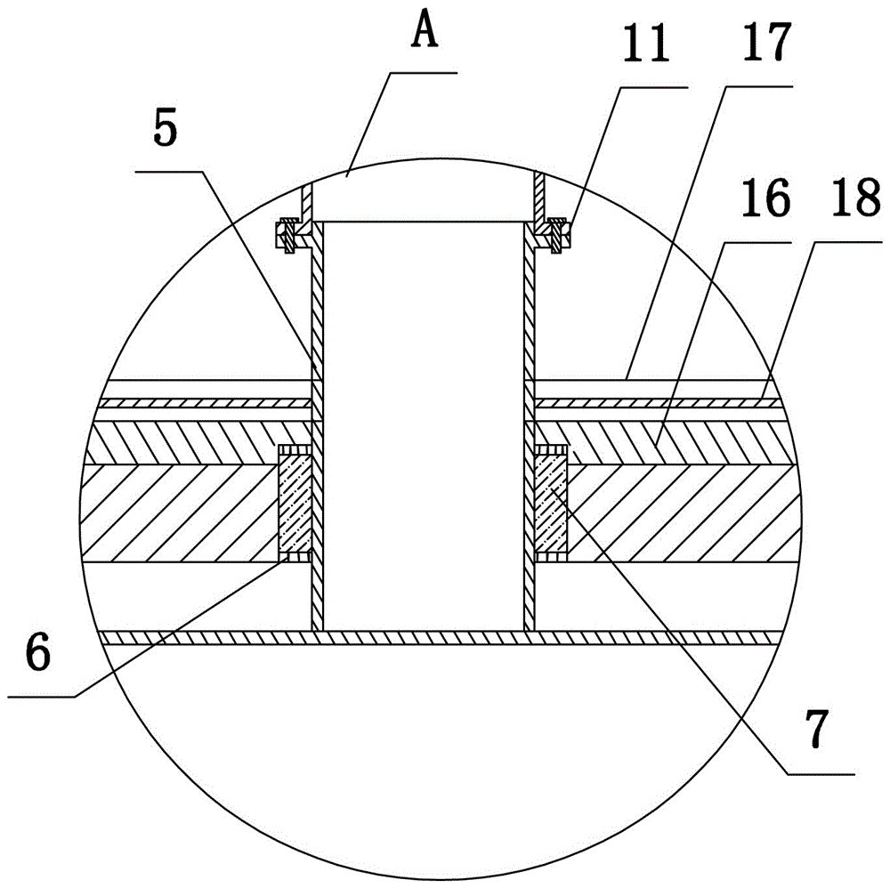
[0031]The present invention includes a rod main body 10, a moisture-proof casing and a shock-proof mechanism arranged in the moisture-proof casing, the moisture-proof casing includes a symmetrically arranged front casing and a rear casing 16, and the front casing and the rear casing 16 are integrally formed with a second flange 17, and the front casing and The inside of the second flange of the rear shell 16 is provided with a sealing strip 18, and the front shell and the rear shell 16 are fastened to each other by bolts 19 to seal and fasten them;

[0032] The anti-shock mechanism includes a support base and a shock-absorbing structure, including a support base 1, a shock-absorbing structure, and a tower main body 10. The main body 10 of the tower tower can use a columnar hollow steel pipe, and the support base 1 is a frustum-shaped structure. The cavity 2 is a rectangular parallelepiped columnar structure, and the upper end surface of the support base 1 is integrally formed w...

Embodiment 3

[0035] The structure of this embodiment is basically the same as that of Embodiment 1, the difference is: as Figure 4 As shown, four first protrusions 12 (two are shown in the figure) are arranged on the outer wall of the shock absorber 4, four second protrusions 13 are arranged on the inner wall of the accommodation cavity 2, and the second disc spring group 9 is four and its two ends are respectively socketed with the first protrusion 12 and the second protrusion 13. During installation, the second disc spring group 9 is retracted through the hydraulic or pneumatic clamping device in the prior art, and it is sleeved on the first protrusion 12 and the second protrusion 13. When an earthquake occurs, this structural design is beneficial The structural stability of the second disc spring group 9 is improved.


PUM


Abstract

The invention discloses a quakeproof pole tower. The quakeproof pole tower comprises a pole body main body (10), a moisture-proof case and a quakeproof mechanism arranged in the moisture-proof case, the quakeproof mechanism comprises a supporting base (1) and a shock absorption structure, an accommodation cavity (2) is formed in the center of the supporting base (1), a cover plate (3) is arranged on the upper end face of the supporting base (1), a through hole is formed in the center of the cover plate (3), the shock absorption structure comprises a shock absorption seat (4) and a connecting rod (5), the shock absorption seat (4) is arranged in the accommodation cavity (2), the upper end of the connecting rod (5) extends out of the through hole, a buffer spring is arranged between the connecting rod (5) and the cover plate (3), and multiple disc spring buffer parts are arranged between the shock absorption seat (4) and the accommodation cavity (2). According to the quakeproof pole tower, through the arrangement of the disc spring buffer parts between the supporting base and the shock absorption seat and the arrangement of the buffer spring between the connecting rod and the cover plate, the stiffness damage of transverse waves and longitudinal waves in an earthquake to a pole are effectively prevented.

Description

technical field [0001] The invention belongs to the technical field of power transmission lines, in particular to an anti-vibration tower. Background technique [0002] At present, the tower design and structural safety and stability construction of 35KV and below power transmission and distribution lines in the power grid are relatively weak. The towers for power transmission and wiring are all equipped with thick cylinders at the bottom, with brackets at the top, and tree-like shapes at high altitude. It is suitable for erecting wires and cables, the bottom of which is connected by bolts to the foundation that is simply laid underground. However, this traditional rigid fixing method between the tower and the ground is difficult to resist the vibration of the foundation or the occurrence of earthquake disasters. When an earthquake occurs, the foundation is often cracked and damaged. Uneven settlement, etc.; when natural disasters such as strong winds, heavy snow, heavy rain...

Claims


Application Information

Patent Timeline
Patent Type & Authority Applications(China)
IPC IPC(8): E04H12/22
CPCE04H12/2269
Inventor 赵志健施学召李峰
Owner STATE GRID HENAN ELECTRIC ZHOUKOU POWER SUPPLY
Why Eureka
Try Eureka