Push rod type dividing device

A shunting device and push rod type technology, applied in the direction of conveyor control device, transportation and packaging, conveyor, etc., can solve the problems of poor reliability, complexity, and large structure of the separation device, and achieve low cost, reasonable and compact structure, Good feed stability

Inactive Publication Date: 2017-05-31
TONGXIANG GREENCITY FLOCKING
View PDF3 Cites 1 Cited by
  • Summary
  • Abstract
  • Description
  • Claims
  • Application Information

AI Technical Summary

Problems solved by technology

At present, the branching device generally divides the workpieces supplied to the material path into two paths. If it needs to be divided into three, four or more paths, the structure of the separation device will be huge and complicated, and the reliability will be poor.

Method used


Image

  • Push rod type dividing device
  • Push rod type dividing device

Examples


Embodiment Construction

[0012] The present invention will be further described in detail below in conjunction with the accompanying drawings and examples. The following examples are explanations of the present invention and the present invention is not limited to the following examples.

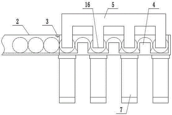
[0013] like figure 1 and figure 2 As shown, a push rod type branching device includes a frame 1, a supply channel 2, a detection probe 3, a fixed baffle 4, a movable baffle 5, a sliding support 6, a branch channel 7, and a connecting plate 8 , push rod 9, support guide rail 10, lever 11, first lug 12, second lug 13, support pin 14, drive cylinder 15, the right end of described supply channel 2 is equidistantly provided with fixed baffle 4, The movable baffle 5 can be slid up and down on the sliding support 6, and the lower end of the movable baffle 5 is provided with an insert stopper 16, and the number of the insert stopper 16 is three or more. The insert block 16 and the fixed baffle 4 are arranged at intervals...


PUM


Abstract

The invention provides a push rod type dividing device, and belongs to the technical field of feeding machines. The push rod type dividing device comprises a feeding material way, a detecting probe, fixed baffles, a movable baffle, a diving material way, a connecting plate, a pushing rod and a lever. The fixed baffles are arranged at the right end of the feeding material way at equal intervals, the movable baffle is arranged on a sliding support in a vertically-sliding manner, insertion sheet stopping blocks are arranged at the lower end of the movable baffle, and the insertion sheet stopping blocks and the fixed baffles are arranged at intervals; the diving material way is arranged on one side of the feeding material way, the detecting probe is installed on the feeding material way, and the connecting plate is arranged on a support guide rail in a front-and-back sliding manner; a piston rod of a driving air cylinder is connected with the connecting plate, the push rod is installed on the connecting plate, and the middle end of the lever is hinged to a rack through a bearing pin shaft; and a first support lug is inserted into a U-shaped groove in the lower end of the lever, and the other end of the lever is attached to the lower end of a second support lug of the movable baffle. By means of the push rod type dividing device, workpieces in the feeding material way are divided into three or more branch material ways, the structure is reasonable and small, cost is low, and the feeding stability is good.

Description

technical field [0001] The invention relates to the technical field of feeders, in particular to a push rod type branching device. Background technique [0002] Feeding machine, also known as feeding machine, refers to a machine that can uniformly, regularly and continuously feed bulk and granular materials from the storage bin to the receiving device during the production process. Statistics show that in the process of workpiece processing and assembly, the cost of supply, loading, unloading and handling of workpieces accounts for more than 1 / 3 of the total cost, and the man-hours account for more than 2 / 3 of the total man-hours. And the vast majority of accidents occur in these processes. Especially in the occasion of batch mass production, when high productivity is required and the mobile working hours are very short, loading and unloading is a repetitive and heavy operation. Therefore, in order to improve production efficiency, reduce the labor intensity of operators, ...

Claims


Application Information

Patent Timeline
IPC IPC(8): B65G47/82B65G43/08
CPCB65G43/08B65G47/82B65G2203/0241B65G2203/0266
Inventor 姚金坤
Owner TONGXIANG GREENCITY FLOCKING
Why Eureka
Try Eureka