A jet printing machine and printed circuit board jet printing system
A technology for printed circuit boards and inkjet printers, applied in printing, typewriters, etc., can solve the problems of low work efficiency, poor use effect, waste of human resources, etc., and achieve improved work efficiency, better use effect, and compact structure Effect
- Summary
- Abstract
- Description
- Claims
- Application Information
AI Technical Summary
Problems solved by technology
Method used
Image
Examples
Embodiment 1
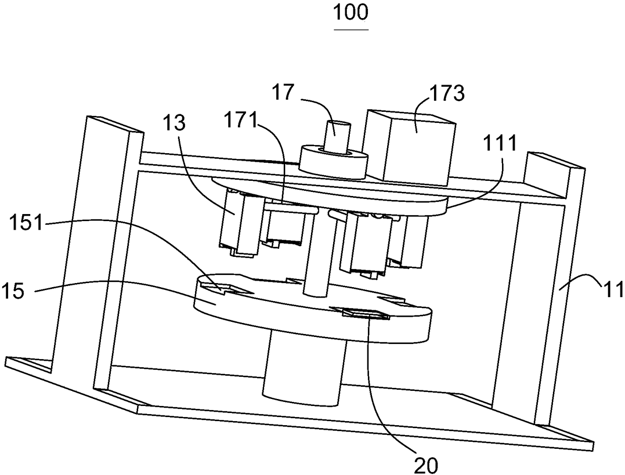
[0038] Please refer to figure 1 , this embodiment provides a jet printer 100 , which includes a base 11 , a jet head assembly 13 and a working turntable 15 .
[0039] The number of nozzle assemblies 13 is at least three and is used for inkjet printing on printed circuit board 20. The axial direction is slidably connected to the base 11. The side of the working turntable 15 close to the nozzle assembly 13 is provided with an embedding groove 151 corresponding to the nozzle assembly 13. The embedding groove 151 is used for embedding the printed circuit board 20. The nozzle The assembly 13 can approach or move away from the embedding groove 151 along the axial direction of the rotating shaft 17 .
[0040] figure 1 The number of the spray head assemblies 13 shown in the figure is four, and may be three, five, or more in a specific implementation.
[0041] It should be noted here that the spray head assembly 13 can approach or stay away from the embedding groove 151. When it is fa...
Embodiment 2
[0066] This embodiment also provides a jet printer 100 , the technical solution described in Embodiment 1 is also applicable to this embodiment, and the disclosed technical solution in Embodiment 1 will not be described again.
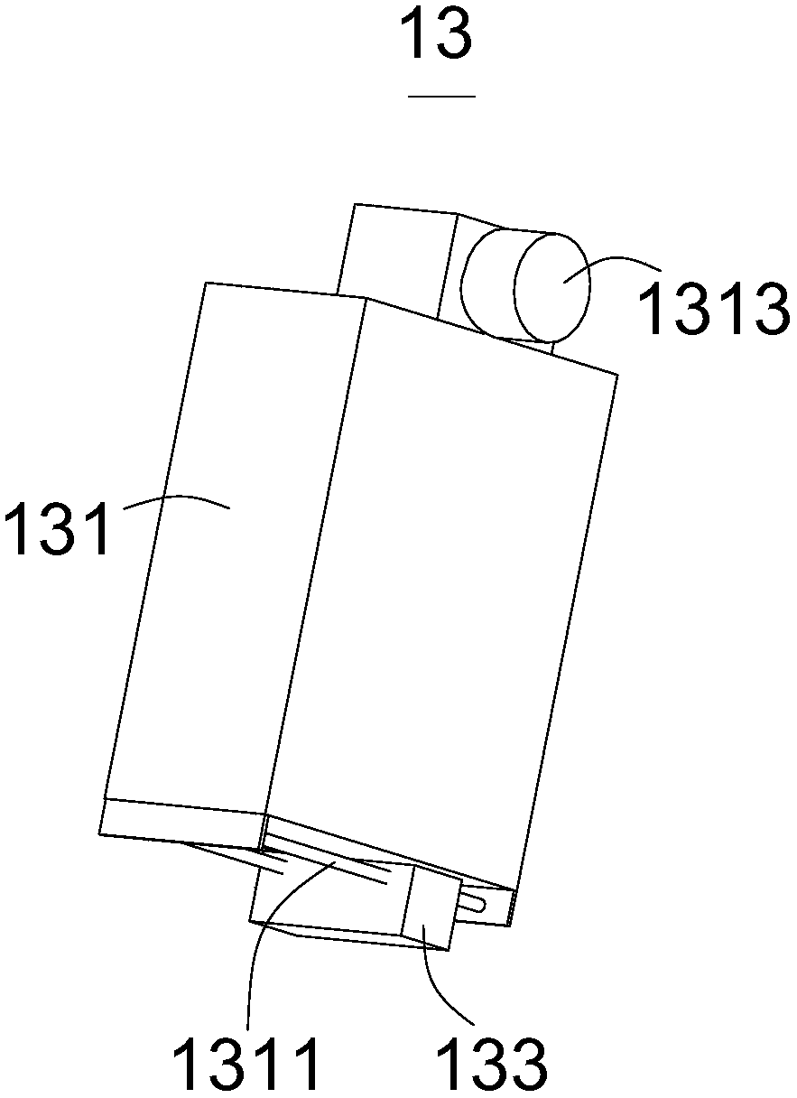
[0067] Please refer to Figure 5 Specifically, the difference between this embodiment and Embodiment 1 is that the nozzle assembly 13 includes a nozzle body 131 and a nozzle part 133. The board 20 is inkjet printed. The nozzle body 131 includes a first part 1301 relatively far away from the working turntable 15 and a second part 1302 relatively close to the working turntable 15. The first part 1301 is slidably connected to the second part along the axial direction of the rotating shaft 17. 1302 , the first part 1301 is connected to the connecting part 171 , and the spray head part 133 is connected to the second part 1302 and is located on a side of the second part 1302 close to the working turntable 15 .
[0068] The structure of the first part 1301 a...
Embodiment 3
[0070] This embodiment also provides a printed circuit board 20 jet printing system, which includes the aforementioned jet printer 100 and has all the functions of the jet printer 100 . The structure of the jet printer 100 can refer to Embodiment 1 or 2.
[0071] In summary, the present invention provides a jet printer 100, which can simultaneously perform inkjet printing on printed circuit boards 20 through at least three nozzle assemblies 13, when multiple printed circuit boards 20 When placed in the embedded groove 151, during the synchronous rotation of the nozzle assembly 13 and the working turntable 15, each nozzle assembly 13 processes the corresponding printed circuit board 20. The overall process is cyclical and does not require much manpower Resources and work efficiency have been greatly improved, and the use effect is better. The design is reasonable, the mechanism is compact, and the market application potential is huge.
PUM
 Abstract
Description
Claims
Application Information
 - R&D
- Intellectual Property
- Life Sciences
- Materials
- Tech Scout
- Unparalleled Data Quality
- Higher Quality Content
- 60% Fewer Hallucinations
Browse by: Latest US Patents, China's latest patents, Technical Efficacy Thesaurus, Application Domain, Technology Topic, Popular Technical Reports.
© 2025 PatSnap. All rights reserved.Legal|Privacy policy|Modern Slavery Act Transparency Statement|Sitemap|About US| Contact US: help@patsnap.com


