
Grinding wheel type metal cutter

A cutting machine and grinding wheel technology, used in metal processing equipment, grinding machines, grinding/polishing equipment, etc., can solve the problems of easy scalding of the skin, poor working conditions, poor quality of manual cutting, etc., to avoid accidental cuts and prevent splash effect

Inactive Publication Date: 2017-05-31
WUXI CAIYUN MACHINERY & EQUIP
View PDF6 Cites 2 Cited by
  • Summary
  • Abstract
  • Description
  • Claims
  • Application Information

AI Technical Summary

Problems solved by technology

[0002] In the process of mechanical processing, the traditional method of plate cutting is manual cutting, which is flexible and convenient, but the quality of manual cutting is poor, the size error is large, the material waste is large, and the follow-up processing workload is large. At the same time, the working conditions are harsh and the production efficiency is low. With the development of the modern mechanical processing industry and the continuous improvement of the cutting quality and precision requirements, the traditional manual has been difficult to meet the needs of production and life, and then there are cutting equipment suitable for different occasions and different materials, and the metal cutting machine is one of them. A kind of cutting equipment commonly used in the processing of metal products. The general grinding wheel metal cutting machine is fully open, which generates a lot of flying chips and dust during the working process, which seriously affects the working environment and health of the staff. It is easy to burn the skin and even cause a fire, and the exposed grinding wheel is easy to cause cuts when children play

Method used


Image

  • Grinding wheel type metal cutter
  • Grinding wheel type metal cutter

Examples


Embodiment Construction

[0013] The following will clearly and completely describe the technical solutions in the embodiments of the present invention with reference to the accompanying drawings in the embodiments of the present invention. Obviously, the described embodiments are only some, not all, embodiments of the present invention. Based on the embodiments of the present invention, all other embodiments obtained by persons of ordinary skill in the art without making creative efforts belong to the protection scope of the present invention.

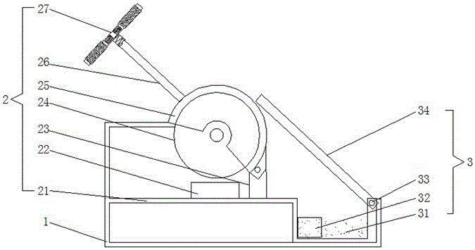
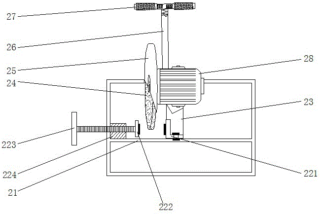
[0014] see Figure 1-2 , the present invention provides a technical solution: a grinding wheel metal cutting machine, including a basic shell 1, the bottom of the left and right sides of the inner cavity of the basic shell 1 are respectively provided with a cutting device 2 and a collecting device 3, and the cutting device 2 includes a cutting table 21 , the upper surface of the cutting table 21 is provided with a clamp 22, the clamp 22 includes an L-shaped fi...


PUM


Abstract

The invention discloses a grinding wheel type metal cutter, comprising a basic outer shell, wherein the bottom parts of left and right sides of the inner cavity of the basic outer shell are respectively provided with a cutting device and a collecting device; the cutting device comprises a cutting platform, and the upper surface of the cutting platform is provided with a clamp; the outside of the clamp is fixedly connected with a supporting pillar, and the supporting pillar is moveably connected with a protecting shell at the top part through a nut; the collecting device comprises a condensing pond, wherein one side of the condensing pond is fixedly connected with the cutting platform, and the other side thereof is connected with a moving baffle through a nut. Through the basic outer shell, the protecting shell and the moving baffle, the working space of the grinding wheel type metal cutter is completely sealed; through the cooperation of the condensing pond and the moving baffle in the collecting device, the spluttered hot scrap irons directly enter the condensing pond and finally absorbed by a permanent magnet block through cooling of the condensing fluid, thereby reaching the effects of cooling and collecting scrap irons.

Description

technical field [0001] The invention relates to the technical field of processing metal products, in particular to a grinding wheel type metal cutting machine. Background technique [0002] In the process of mechanical processing, the traditional method of plate cutting is manual cutting, which is flexible and convenient, but the quality of manual cutting is poor, the size error is large, the material waste is large, and the follow-up processing workload is large. At the same time, the working conditions are harsh and the production efficiency is low. With the development of the modern mechanical processing industry and the continuous improvement of the cutting quality and precision requirements, the traditional manual has been difficult to meet the needs of production and life, and then there are cutting equipment suitable for different occasions and different materials, and the metal cutting machine is one of them. A kind of cutting equipment commonly used in the processin...

Claims


Application Information

Patent Timeline
IPC IPC(8): B24B27/06B24B55/06B24B55/00
CPCB24B27/06B24B55/00B24B55/06
Inventor 倪俊芳
Owner WUXI CAIYUN MACHINERY & EQUIP
Learn More