A feeding device for a punching machine
A technology of feeding device and stamping machine, which is applied in the field of stamping machines, can solve the problems of low production efficiency and achieve the effect of improving production efficiency and facilitating collection
- Summary
- Abstract
- Description
- Claims
- Application Information
AI Technical Summary
Problems solved by technology
Method used
Image


Examples
Embodiment 1
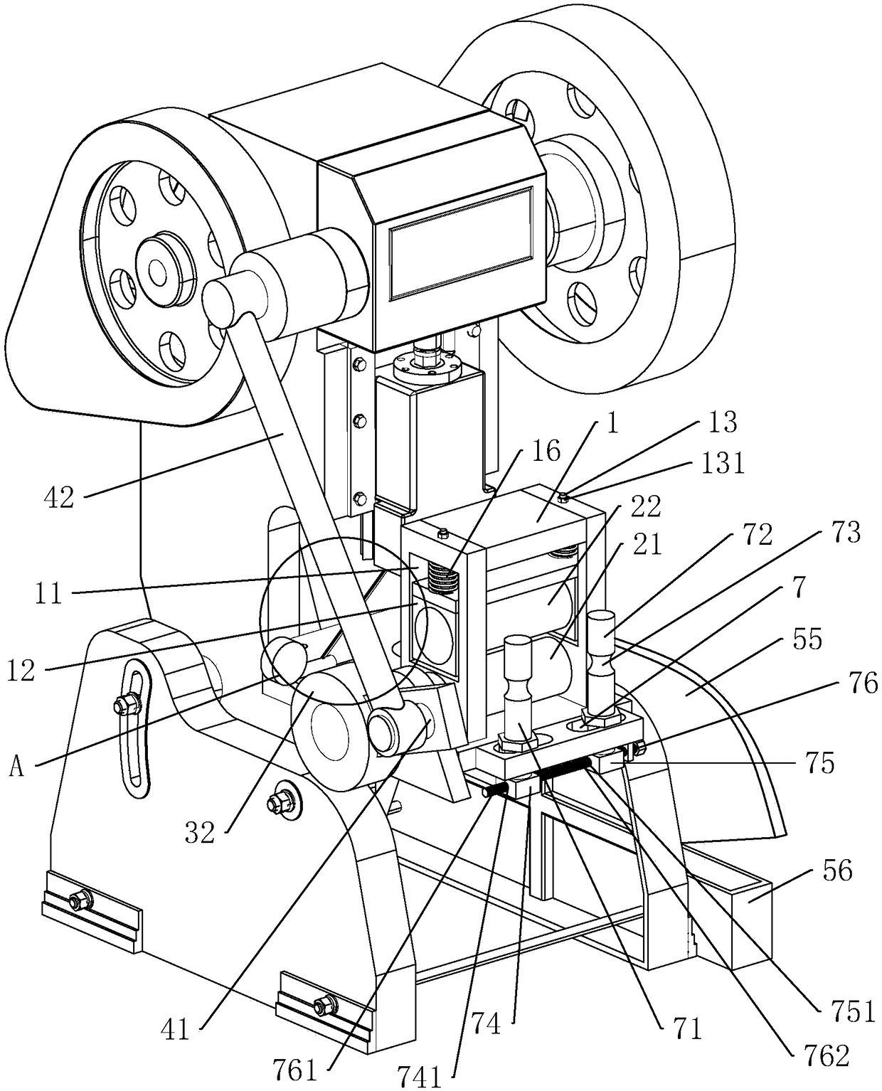
[0036] Embodiment 1: a kind of feeding device for stamping machine, such as figure 1 As shown, it includes a vertically placed frame 1, and the frame 1 is a rectangular parallelepiped frame. The frame 1 is fixed on the workbench of the stamping machine by bolts, and is positioned at the front end of the workbench. Two sliding slots 11 with a rectangular cross section are opened on the side wall of the frame 1, and the sliding slots 11 are arranged along the vertical direction. A guide block 12 arranged as a cuboid is slidably connected in each chute 11 . The cylindrical second pressing roller 22 is rotatably connected to the guide block 12 so that the second pressing roller 22 is placed horizontally.
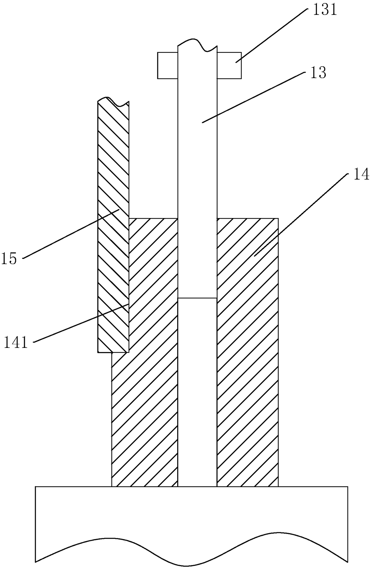
[0037] Such as figure 1 with image 3As shown, the screw rod 13 is rotatably connected to the frame 1 through bearings, the threaded part of the screw rod 13 is placed in the above-mentioned chute 11, and the screw rod 13 is placed vertically. A cylindrical drive pipe 14 is...
Embodiment 2
[0045] Embodiment 2: a kind of feeding device for stamping machine, such as Figure 5 As shown, the difference from Embodiment 1 is that the setting of the first thread 741 and the second thread 751 is omitted (see figure 1 ).
[0046] The crankshaft 8 is fixed on the adjusting rod 76, the first connecting rod 81 and the second connecting rod 82 are hinged on the crankshaft 8, the end of the first connecting rod 81 away from the crankshaft 8 is hinged with the first positioning block 74, and the second connecting rod One end of the rod 82 away from the crankshaft 8 is hinged to the second positioning block 75 .
[0047] When in use, the adjusting rod 76 is rotated to drive the crankshaft 8 to rotate, and through the pulling force of the first connecting rod 81 and the second connecting rod 82, the first positioning block 74 and the second positioning block 75 can be moved towards the direction of mutual approaching at the same time. Moving, at the same time, the guide groove...
Embodiment 3
[0048] Embodiment 3: a kind of feeding device for stamping machine, such as Image 6 As shown, the difference from Embodiment 1 is that the setting of the first thread 741 and the second thread 751 is omitted (see figure 1 ).
[0049] A first gear 91 is fixed on the adjusting rod 76, and a second gear 92 is rotatably connected to the frame 1, and the first gear 91 and the second gear 92 are meshed. A first rack 93 is fixed on the first positioning block 74, a second rack 94 is fixed on the second positioning block 75, the first gear 91 is meshed with the first rack 93, and the second gear 92 and the second gear 92 are engaged. Two tooth racks 94 mesh.
[0050] During use, the adjusting lever 76 is rotated, and the adjusting lever 76 drives the first gear 91 to rotate. At the same time, the first gear 91 drives the second gear 92 to rotate, the second gear 92 drives the second rack 94 to move, and the first gear 91 drives the second gear A rack 93 moves. Thus, the simultane...
PUM
 Abstract
Description
Claims
Application Information
 - Generate Ideas
- Intellectual Property
- Life Sciences
- Materials
- Tech Scout
- Unparalleled Data Quality
- Higher Quality Content
- 60% Fewer Hallucinations
Browse by: Latest US Patents, China's latest patents, Technical Efficacy Thesaurus, Application Domain, Technology Topic, Popular Technical Reports.
© 2025 PatSnap. All rights reserved.Legal|Privacy policy|Modern Slavery Act Transparency Statement|Sitemap|About US| Contact US: help@patsnap.com