
A method of using a spiral half-pipe automatic winding system

A control system and spiral technology, applied in heat exchange equipment and other directions, can solve the problems of uneven pitch of half pipes, frequent manual movement, high labor intensity, etc., and achieve the effect of reducing labor, simple and accurate winding, and reducing human errors.

Active Publication Date: 2018-08-17
CHINA NAT CHEM ENG THIRD CONSTR
View PDF6 Cites 0 Cited by
  • Summary
  • Abstract
  • Description
  • Claims
  • Application Information

AI Technical Summary

Problems solved by technology

However, for the manufacturing process of the spiral half-pipe heat exchanger, the half-pipe forming machine only solves the production problem of the half-pipe. At present, when winding the half-pipe on the equipment cylinder, manual scribing is still used. Adjust the pitch of the half-pipe installation upwards, and the half-pipe forming machine needs frequent manual movement. This operation method also has problems such as high labor intensity, uneven pitch of the half-pipe wound, and low efficiency.

Method used


Image

  • A method of using a spiral half-pipe automatic winding system
  • A method of using a spiral half-pipe automatic winding system
  • A method of using a spiral half-pipe automatic winding system

Examples


Embodiment 1

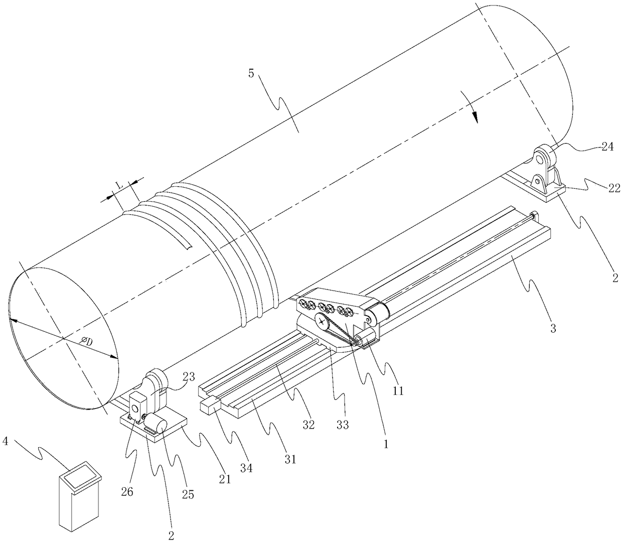
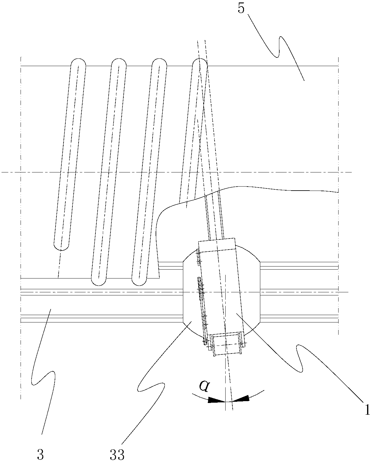
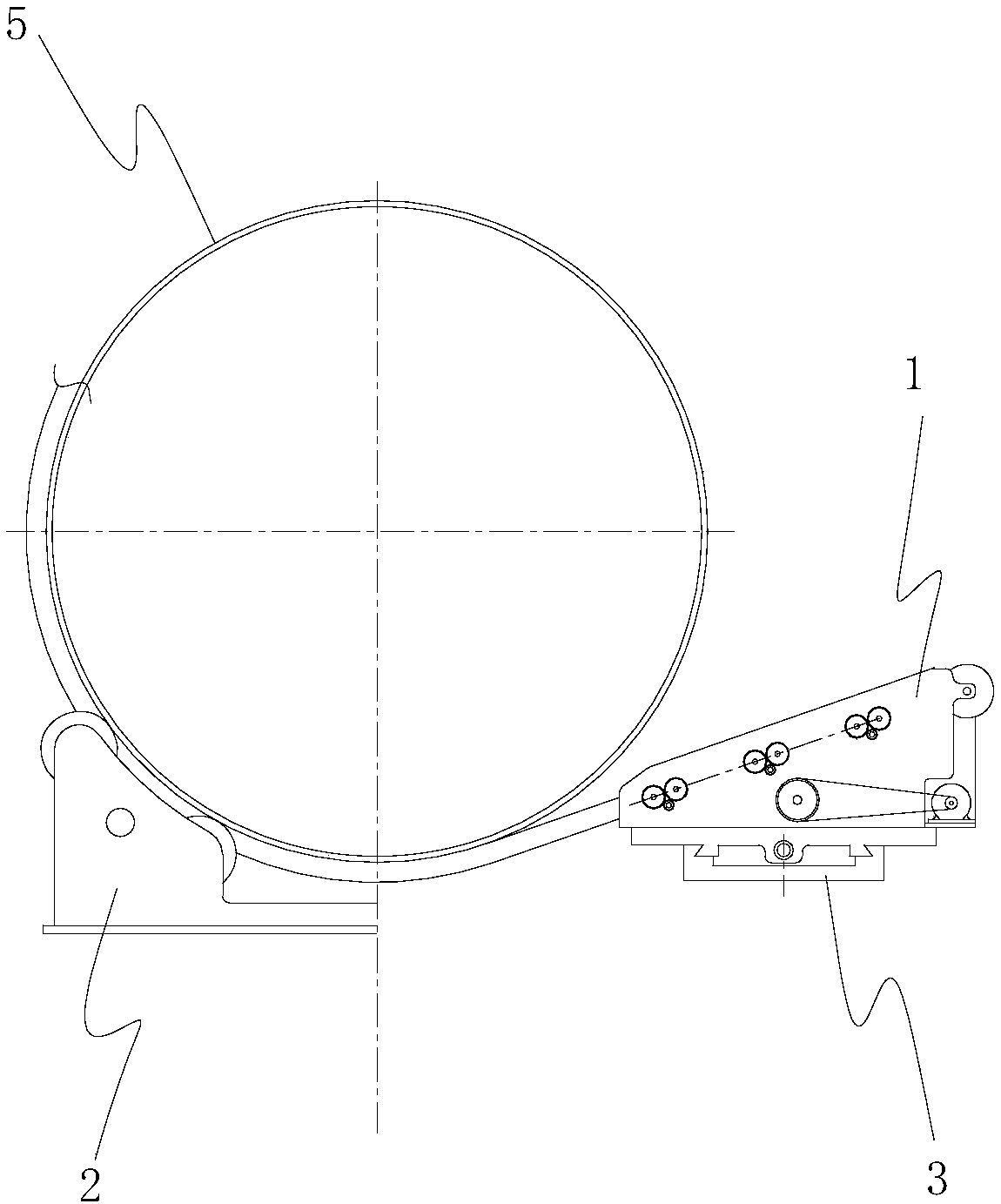
[0040] Such as Figure 1 to Figure 5As shown, the spiral half-pipe automatic winding system in this embodiment includes a half-pipe forming machine 1, a roller frame 2, a half-pipe forming machine walking mechanism 3 and a control system 4, and the half-pipe forming machine 1 is driven by a first motor 11 , the half-pipe forming machine 1 includes a frame, a steel strip introduction device and a half-pipe forming device composed of a concave wheel and a cam that cooperate with each other, and the concave wheel and the cam of the half-pipe forming device are respectively fixed by the concave wheel drive shaft and the cam drive shaft On the frame, the size of the concave wheel and the cam can be replaced, the position of the concave wheel and the cam can be moved, the bending radius of the spiral half pipe and the specification of the half pipe can be adjusted at any time, the operation is convenient, and at least one of the half pipe forming devices The concave wheel is connect...


PUM

PropertyMeasurementUnit
lengthaaaaaaaaaa

Abstract

The invention discloses an application method of an automatic winding system of a half spiral tube, belonging to the technical field of chemical engineering nonstandard equipment manufacture. The application method comprises the steps: mounting and fixing a roller carrier; placing a cylinder on the roller carrier; mounting a half spiral tube molding machine and a half spiral tube molding machine traveling mechanism; adjusting the horizontal discharge angle alpha of the half spiral tube molding machine; in a debugging mode, fitting the bend radius of the rolled half annular tube with the outer wall of the cylinder; then leading the molded half tube to a starting position of winding of the half tube outside the cylinder, welding the front end of the half tube with the cylinder for a section for fixation; starting a first motor, a second motor and a third motor simultaneously, evenly winding the molded half tube around the outer wall of the cylinder, performing spot welding once every 500mm by an electric welder; stopping system operation when the half tube is wound to an end position, cutting the surplus half tube; and welding fillet weld between the half tube and the cylinder to finish winding. The application method can realize automatic winding of the half spiral tube, has a controllable thread pitch and accuracy in winding, and is time-saving, labor-saving, high in efficiency, better in effects in mass production, economical and practical.

Description

technical field [0001] The invention belongs to the technical field of chemical non-standard equipment manufacturing, and more specifically relates to a method for using a spiral half-pipe automatic winding system. Background technique [0002] At present, in my country's chemical, pharmaceutical and food industries, many equipment use half-pipe jackets for heat exchange. For example, the heat exchange devices of fluidized beds used in chemical production, stainless steel fermentation tanks in the pharmaceutical industry, and beer tanks in the wine industry all adopt continuous half-pipes spirally coiled on the tank shell, and are welded with the cylinder to form a Channel, the medium exchanges heat with the material in the equipment in the channel, and the semi-pipe jacket structure has the advantages of increasing the capacity of the heat exchange equipment, avoiding pollution during material heat exchange, and at the same time increasing the strength and rigidity of the e...

Claims


Application Information

Patent Timeline
Patent Type & Authority Patents(China)
IPC IPC(8): B21D11/06B21D11/22B21D53/06
CPCB21D11/06B21D11/22B21D53/06
Inventor 李文蔚
Owner CHINA NAT CHEM ENG THIRD CONSTR
Learn More