
3D printing method and device for manufacturing micro-fluidic chip by utilizing nanometer fiber paper base laminate

A microfluidic chip and nanofiber technology, which is applied in the directions of additive manufacturing, manufacturing tools, chemical instruments and methods, can solve the problems of difficulty in popularization and application, hidden safety hazards, and high requirements for folding accuracy, and achieves a simple, fast and economical process. The effect of manufacturing cost, simple and flexible method

Inactive Publication Date: 2017-05-31
XIAMEN UNIV
View PDF6 Cites 22 Cited by
  • Summary
  • Abstract
  • Description
  • Claims
  • Application Information

AI Technical Summary

Problems solved by technology

[0005] However, 3D printing microfluidic chips are still facing bottlenecks and challenges in many aspects: First, the cost. The cost of existing 3D printers is generally relatively expensive, which brings difficulties to their further popularization and application.
The second is printing materials. At present, most of the molding materials for 3D printing use chemical polymers, the selection is limited, the physical properties of the molded products are poor, and there are certain hidden dangers in terms of safety.
[0007] At present, the manufacture of paper-based microfluidic chips is mostly a two-dimensional structure on a single-layer paper base, or some 3D structures with relatively simple structures are realized by folding a single-layer paper base. High, and additional clamping devices are required to reduce the gap between layers (David M.Cate, Jaclyn A.Adkins, JaruwanMettakoonpitak, and Charles S.Henry.Recent Developments in Paper-Based Microfluidic Devices.Analytical Chemistry,2015, 87(1),19–41)

Method used


Image

  • 3D printing method and device for manufacturing micro-fluidic chip by utilizing nanometer fiber paper base laminate
  • 3D printing method and device for manufacturing micro-fluidic chip by utilizing nanometer fiber paper base laminate

Examples


Embodiment Construction

[0025] The present invention will be further described below in conjunction with drawings and embodiments.

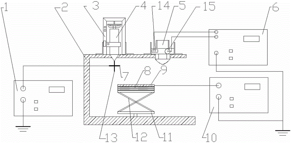
[0026] see figure 1 with 2 , the embodiment of the 3D printing device for manufacturing microfluidic chips by lamination of nanofiber paper base is provided with a DC power supply 1, a frame 2, a two-dimensional jet printing motion platform 11, a feed pump 3, a spinning needle 13, a liquid storage Syringe 4, 3D printing nozzle 5, auxiliary power supply 10, temperature control device 6, conductive substrate 7, insulating plate 8, collecting plate 9 and lifting platform 12.

[0027] The liquid storage syringe 4 is fixedly connected with the spinning needle 13, the liquid storage syringe 4 is fixed on the feed pump 3 through a clamping mechanism, and the feed pump 3 controls the supply of the polyimide solution in the liquid storage syringe 4 speed, so that the polyimide solution enters the spinning needle 13 continuously and evenly. The conductive substrate 7 is fixed ...


PUM


Abstract

The invention provides a 3D printing method and device for manufacturing a micro-fluidic chip by utilizing a nanometer fiber paper base laminate, relating to micro-fluidic chips. The 3D printing method comprises the following steps: 1) depositing a nanometer fiber paper base on a collecting plate; 2) moving the collecting plate into a hydrophobic material jet printing area, heating for maintaining the hydrophobic material in a sprayer to be in a molten state, adding into an electric field, and downward jetting the hydrophobic material fiber, thereby forming a hydrophobic material fiber pattern; 3) designing each layer of hydrophobic material fiber pattern, and constructing the structure of the micro-fluidic chip in a 3D printing manner of continuously overlapping the nanometer fiber paper base and the hydrophobic material fiber pattern; and 4) heating the collecting plate, permeating each layer of hydrophobic material into the nanometer fiber paper base, constructing a micro-fluidic control structure, and finally forming the micro-fluidic chip with the 3D structure on the nanometer fiber paper base. The printing device is provided with a direct current power supply, a two-dimension jet printing motion platform, a feeding pump, a spinning needle, a liquid storage needle drum, a jet, an auxiliary power supply, a temperature control device, a conductive substrate, an insulating plate, the collecting plate and a lifting platform.

Description

technical field [0001] The invention relates to a microfluidic chip, in particular to a 3D printing method and device for manufacturing a microfluidic chip by stacking nanofiber paper bases. Background technique [0002] The term microfluidics appeared in the early 1990s and refers to the technology of manipulating and controlling fluids on the micron scale. After more than 20 years of development, microfluidic technology has developed from the initial single-function fluid control device to the current multi-functional integrated and widely used microfluidic chip technology, which is used in analytical chemistry, medical diagnosis, cell screening, gene analysis, Drug delivery and other fields have been widely used. Compared with traditional methods, microfluidic technology has the characteristics of small size, fast detection speed, small reagent consumption, low cost, multi-functional integration, and high throughput. [0003] In recent years, more and more researchers h...

Claims


Application Information

Patent Timeline
Patent Type & Authority Applications(China)
IPC IPC(8): B01L3/00B29C64/118B29C64/20B33Y10/00B33Y30/00
CPCB01L3/502707B01L2200/12B01L2300/12B01L2300/165B33Y10/00B33Y30/00
Inventor 孙道恒张鹏程王凌云赵扬陈沁楠吴德志林立伟
Owner XIAMEN UNIV
Learn More