
A walking device for a bait throwing system

A technology of walking device and bait throwing machine, which is applied in application, climate change adaptation, fish farming, etc., and can solve problems such as high difficulty in control, power loss, and complicated towing control lines

Active Publication Date: 2022-04-12
NINGBO UNIV
View PDF12 Cites 0 Cited by
  • Summary
  • Abstract
  • Description
  • Claims
  • Application Information

AI Technical Summary

Problems solved by technology

However, the existing bait feeding system has the following problems: the horizontal traveling mechanism and the longitudinal traveling mechanism in the traveling device are arranged vertically and horizontally, the control circuit of the tow is complicated, and the traveling device must frequently carry out single-point positioning and multi-directional walking, which not only causes mechanical wear , power loss, and low bait casting efficiency, high difficulty in control

Method used


Image

  • A walking device for a bait throwing system
  • A walking device for a bait throwing system
  • A walking device for a bait throwing system

Examples


Embodiment 1

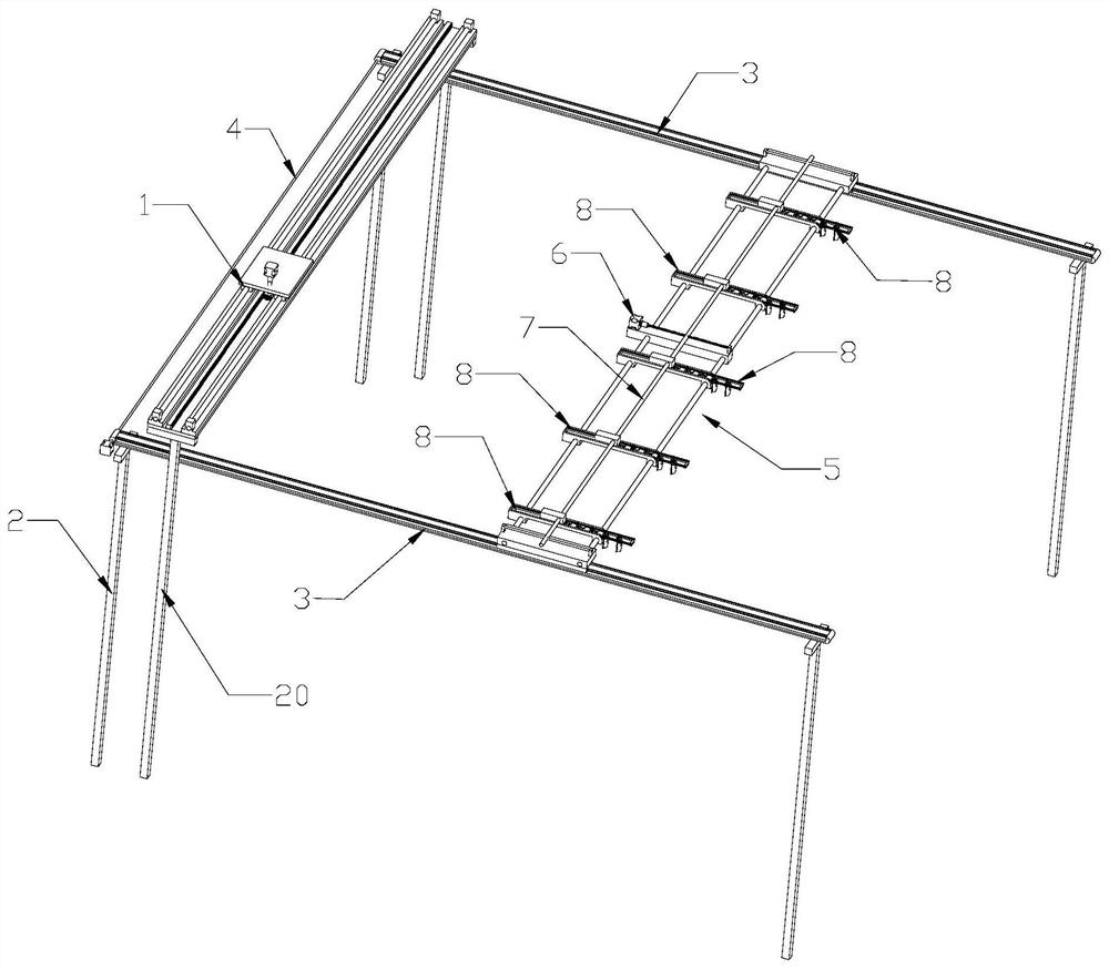
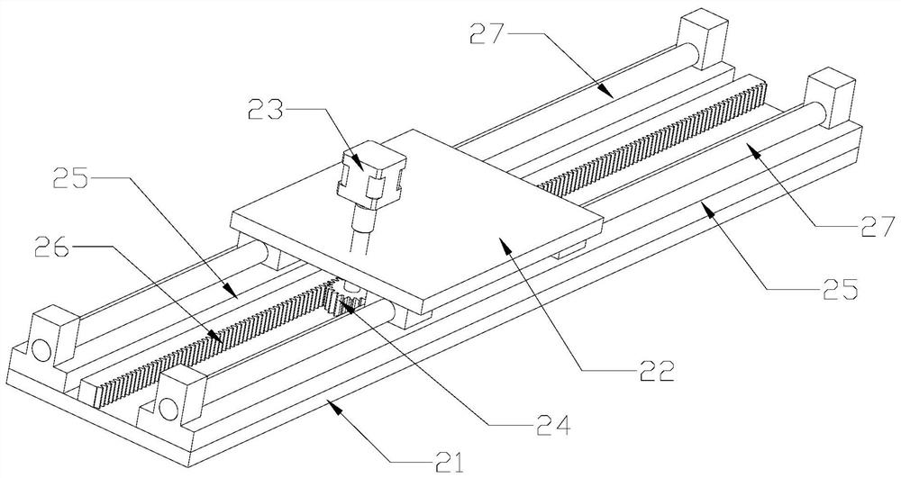
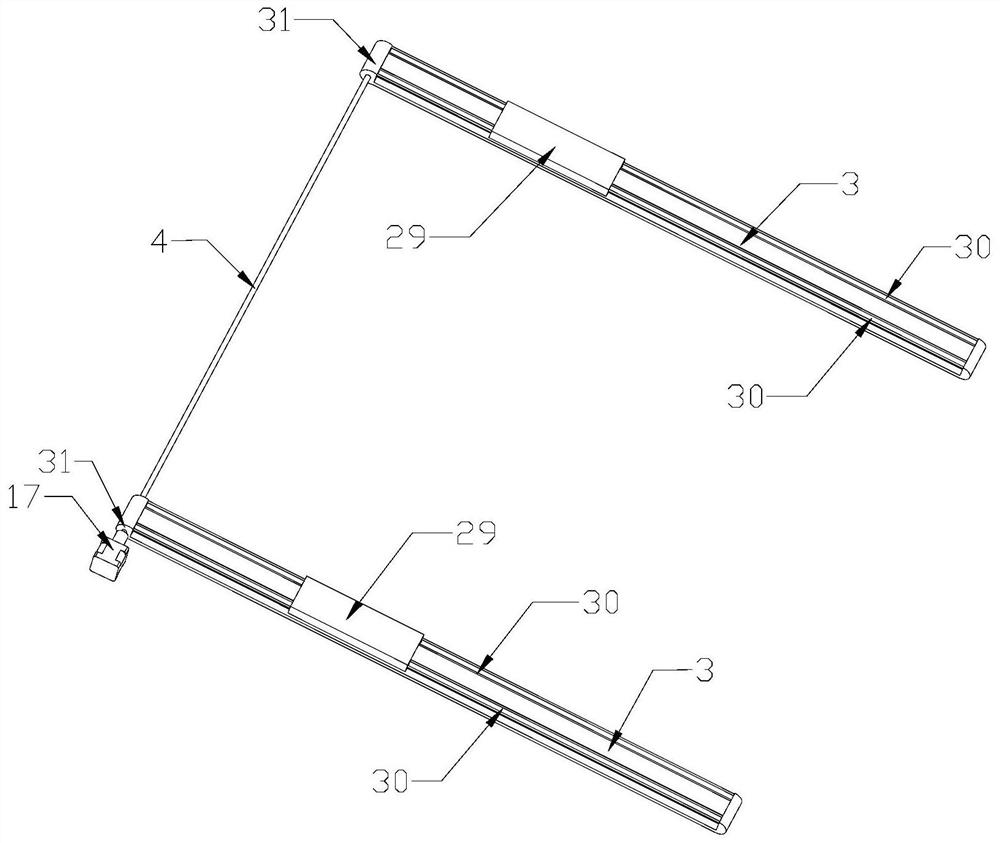
[0024]Embodiment 1: As shown in the figure, a running device of a bait casting system includes a longitudinal running mechanism 1 and a lateral running mechanism, the lateral running mechanism includes at least one lateral running assembly, and the lateral running assembly includes a first support 2, two conveyor belts. 3. The first motor 17, the first synchronous connection shaft 4 and the feeding unit 5, the two conveyor belts 3 are arranged on the first bracket 2 in parallel and at intervals, and the two conveyor belts 3 extend to the bottom of the longitudinal traveling mechanism 1. The conveying direction of the conveyor belt 3 Perpendicular to the conveying direction of the longitudinal traveling mechanism 1 , one end of each conveying belt 3 has a conveying shaft 31 , the conveying shafts 31 of the two conveying belts 3 are connected by the first synchronous connecting shaft 4 , the output shaft of the first motor 17 is The transmission shaft 31 is connected, and the fee...

Embodiment 2

[0031] Embodiment 2: As shown in the figure, a running device of a bait-casting system includes a longitudinal running mechanism 1 and a lateral running mechanism, the lateral running mechanism includes at least one lateral running assembly, and the lateral running assembly includes a first support 2, two conveyor belts. 3. The first motor 17, the first synchronous connection shaft 4 and the feeding unit 5, the two conveyor belts 3 are arranged on the first bracket 2 in parallel and at intervals, and the two conveyor belts 3 extend to the bottom of the longitudinal traveling mechanism 1. The conveying direction of the conveyor belt 3 Perpendicular to the conveying direction of the longitudinal traveling mechanism 1 , one end of each conveying belt 3 has a conveying shaft 31 , the conveying shafts 31 of the two conveying belts 3 are connected by the first synchronous connecting shaft 4 , the output shaft of the first motor 17 is The transmission shaft 31 is connected, and the fe...


PUM


Abstract

The invention discloses a walking device of a bait throwing system, which comprises a longitudinal traveling mechanism and a transverse traveling mechanism. The synchronous connection shaft and the feeding unit, two conveyor belts are arranged on the first bracket at intervals in parallel, one end of each conveyor belt has a transmission shaft, the transmission shafts of the two conveyor belts are connected through the first synchronous connection shaft, the output shaft of the first motor and a The transmission shaft of the conveyor belt is connected, and the feeding unit includes a second motor, a second synchronous connection shaft, a sliding track and a plurality of distributing modules distributed on the sliding track at intervals, the sliding track is arranged on two conveyor belts, and the output of the second motor The shaft is connected to the second synchronous connection shaft, and each distribution module includes a distribution track, a distribution frame and n distribution bins; the advantages are simple line layout, single walking path, small mechanical wear, small power loss and low power consumption. The bait is more efficient.

Description

technical field [0001] The present invention relates to a traveling device, in particular to a traveling device of a bait casting system. Background technique [0002] Circulating water basket culture technology has been widely used in the industrial seafood aquaculture industry. The traditional feeding method of circulating water basket aquaculture farms is mainly manual feeding, which not only consumes manpower, material resources and financial resources, but also causes low feeding efficiency, waste of bait, water pollution and death of aquaculture products. problem, which has been replaced by a more automated baiting system. [0003] The existing bait casting system includes a control system, a running device and a bait casting machine. The running device includes a lateral running mechanism and a longitudinal running mechanism, and the longitudinal running mechanism includes two running rails. The traveling mechanism includes a sliding rod perpendicular to the running...

Claims


Application Information

Patent Timeline
Patent Type & Authority Patents(China)
IPC IPC(8): A01K61/80
CPCA01K61/00Y02A40/81
Inventor 蔡永胜张刚魏超段玉贺
Owner NINGBO UNIV
Learn More