
Silage whole-plant harvest and silage ear stem harvest inclusive type corn machine

A compatible corn machine technology, applied to harvesters, agricultural machinery and tools, threshing equipment, etc., can solve problems such as short operation time, blockage of ear picking road, and small row spacing of corn plants, so as to increase extra income and work time The effect of extension and user income increase

Active Publication Date: 2017-05-31
QINGDAO LONGSHUO FARMING MACHINERY MFG
View PDF8 Cites 6 Cited by
  • Summary
  • Abstract
  • Description
  • Claims
  • Application Information

AI Technical Summary

Problems solved by technology

[0002] The corn harvesters currently on the market can only achieve simple harvesting of corn or combined harvesting of corn ears and stalks (both ears and stems are harvested while corn stalks are crushed and recycled), and they do not have the ability to harvest whole plants of silage (that is, corn ears together with corn Straw crushing and recycling) function, and most ear and stem harvesters have more harvesting restrictions, such as: corn plant row spacing is too small, too many weeds in the field and other factors cannot be harvested smoothly, and this type of ear stem harvester During normal harvesting, the fringe picking path is often blocked due to factors such as the stalks being tilted, the gap between the clamping chain is too large, and the adjustment gap of the stem roller is not suitable, and the frequency of blockage is high. For fear of wasting time, the user does not shut down the machine to clean the blockage directly, so there is a great personal safety hazard, and this type of model has a single function and no other expansion functions, so the operation time is generally short, and the general harvest cycle is 10-15 days , users earn less
[0003] At this stage, there are many kinds of patented technologies for harvesting corn harvester with both ears and stems in the market, but they do not have the function of harvesting the whole plant of silage, and the realization of the function of harvesting ears and stems is relatively large.
The patent number is 201110183101.3, and the name is "separated storage, top support, synchronous crushing, self-propelled corn harvester with both ears and stems". The bottom of the corn plant is cut off, and then the corn plant is clamped to the ear-picking roller by the clamping chain at the rear end of the cutter. The ear-picking roller picks the corn ears and then pulls the corn stalks to the knife box located at the lower end of the ear-picking roller. The knife box After the corn stalks are chopped, they fall into the grass collector under the knife box, and then the conveying auger in the grass collector pushes the chopped straw to the fan located on the side of the cutting table. The negative pressure generated by the fan through high-speed rotation The crushed straw is blown to the grass bin at the rear end of the harvester through the sprinkler, and the ears of corn are transported through a series of conveyors and finally sent to the granary at the rear end of the harvester, so as to realize the harvest of corn ears and stems. Corn harvesting has relatively large limitations. For example, if there are too many weeds in the planting field, it is easy to block the ear inlet channel, resulting in blockage during harvesting; if corn plants are lodging, they cannot be harvested, and corn plants cannot be harvested if the row spacing of corn plants is less than 550mm, which has great limitations.

Method used


Image

  • Silage whole-plant harvest and silage ear stem harvest inclusive type corn machine
  • Silage whole-plant harvest and silage ear stem harvest inclusive type corn machine
  • Silage whole-plant harvest and silage ear stem harvest inclusive type corn machine

Examples


Embodiment 1

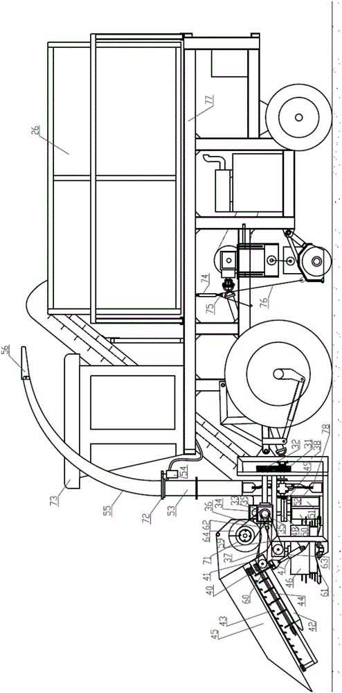
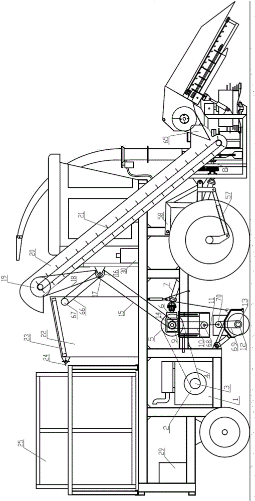
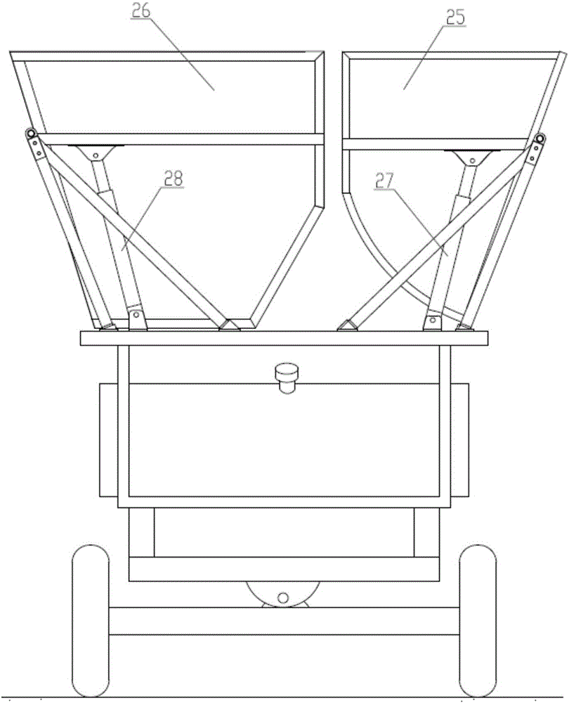
[0031] Such as figure 1 and figure 2 As shown, the corn machine compatible with both silage harvesting and silage ear stem harvesting includes a frame 77, a header harvesting part, an ear elevator part, a field returning device part, a peeling machine part, a power part, and an ear collection part. Box 25 and straw collection box 26, header harvesting part, ear elevator part, returner part, peeling machine part, ear collection box and straw collection box are all arranged on the frame, and header harvesting part is arranged on the frame The front part of the frame, the field return part is set at the bottom of the frame, the bottom end of the ear elevator part is connected with the header harvesting part, the top part of the ear elevator part is connected with the peeler part, and the ear collection box is located in the peeler part the rear. Fruit ear collection box and stalk collection box are all arranged on the rear portion of frame 77.

[0032] Described power part co...

Embodiment 2

[0050] The difference with embodiment 1 is: as Figure 4 As shown, the ear picking system of the header part is dismantled. At this time, the harvester is used to harvest the whole silage plant. The harvesting process is as follows: the straw feeding drum 46 touches the whole corn plant during the operation of the harvester, and the corn plant The root of the corn plant is cut off by the cutter head 61 at the bottom of the drum, and the corn plant with the cut root is pinched into the toothed roller 50 by two stalk feeding rollers 46 rotating in opposite directions. Because the gap between the two rollers of the toothed roller is small, it can be more The corn plant is clamped and sent back to the pre-pressing roller 51. The gap between the two rollers of the pre-pressing roller is very small, and the corn stalks and corn ears can be flattened and then sent to the mower 52. After the corn stalks and corn ears are pulverized synchronously, the cutter impeller 78 blows the chopp...

Embodiment 3

[0054] The difference from Example 1 is that the ear picking system includes a header shield, a reel chain, an ear chain, at least one set of stalk rollers, at least one set of ear picking plates, a stalk puller gear box, and an ear conveying agitator. At the Longhe fruit ear discharge port, a set of ear picking plates with a fixed gap is arranged on the upper end of each set of stem pulling rollers. The two stem pulling rollers rotate at high speed in opposite directions to quickly pull down the corn plant. During the pulling process, the corn ears touch the picking plate. The ear boards are removed after the ears, while the corn stalks continue to be pulled down into the straw feeding system.

[0055] Others are the same as embodiment 1.


PUM


Abstract

The invention relates to core harvest, in particular to a silage whole-plant harvest and silage ear stem harvest inclusive type corn machine. A roller power gearbox is connected with two straw feeding rollers and a roller bottom cutter disc respectively, the bottom of a straw feeding system power gearbox is in power connection with a straw feeding system speed change gearbox, the system speed change gearbox is connected with plate-tooth rollers and prepressing rollers, the plate-tooth rollers are located in the rear of the straw feeding rollers, the prepressing rollers are located in the rear of the plate-tooth rollers, a cutting-table hay cutter is located in the rear of the plate-tooth rollers, a cutter disc impeller is located in the cutting-table hay cutter, the gap ranging from 300mm to 400mm is formed between the neighboring straw feeding rollers right above the cutting-table hay cutter of a tossing system, the gap ranging from 20mm to 30mm is formed between the two neighboring plate-tooth rollers, and the gap ranging from 15mm to 120mm is formed between the two neighboring preprocessing rollers. Silage whole-plant harvest and silage ear stem harvest are included into one harvester, fund for purchasing the harvester is saved for users, operating cycle can be greatly prolonged, and diversified harvest of corn is realized.

Description

technical field [0001] The invention relates to corn harvesting, in particular to a corn machine compatible with both silage whole plant harvesting and yellow silage ear stem harvesting. Background technique [0002] The corn harvesters currently on the market can only achieve simple harvesting of corn or combined harvesting of corn ears and stalks (both ears and stems are harvested while corn stalks are crushed and recycled), and they do not have the ability to harvest whole plants of silage (that is, corn ears together with corn Straw crushing and recycling) function, and most ear and stem harvesters have more harvesting restrictions, such as: corn plant row spacing is too small, too many weeds in the field and other factors cannot be harvested smoothly, and this type of ear stem harvester During normal harvesting, the fringe picking path is often blocked due to factors such as the stalks being tilted, the gap between the clamping chain is too large, and the adjustment gap...

Claims


Application Information

Patent Timeline
Patent Type & Authority Applications(China)
IPC IPC(8): A01D45/02A01F11/06
CPCA01D45/02A01D45/025A01F11/06
Inventor 赵平吕文超孟范俊
Owner QINGDAO LONGSHUO FARMING MACHINERY MFG
Learn More