Moving-magnet type loudspeaker
A loudspeaker, moving magnet technology, used in sensors, loudspeakers, electrical components, etc., can solve the problems of inability to meet ultra-thin portable electronic equipment, low high-frequency performance, poor high-frequency transient response, etc. Improve the effect of poor high-frequency transient response, improve high-frequency performance, and facilitate adjustment
- Summary
- Abstract
- Description
- Claims
- Application Information
AI Technical Summary
Problems solved by technology
Method used
Image
Examples
Embodiment 1
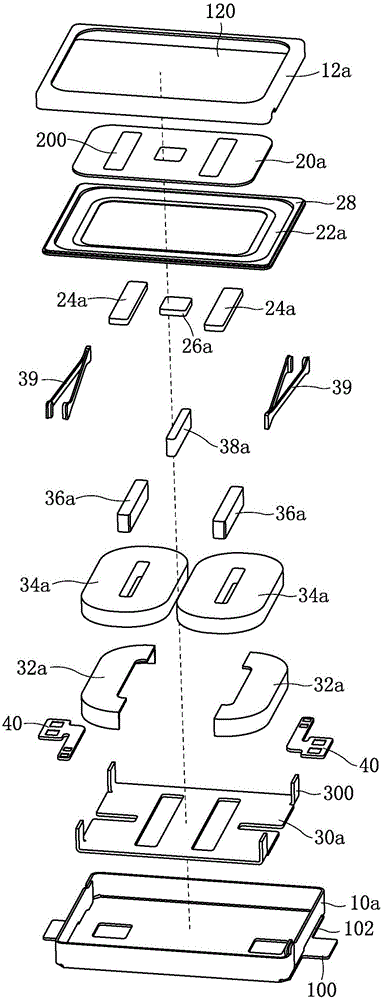
[0039] Such as figure 1 and figure 2 As shown together, a moving magnet loudspeaker has a rectangular parallelepiped structure, including a casing, a diaphragm and a vibrator accommodated in the casing, and the diaphragm and the vibrator are arranged in parallel. The casing includes a front cover 12a and a casing 10a that are combined up and down. The front cover 12a is a box-shaped structure with an open lower end, and the casing 10a is a box-shaped structure with an open upper end. The open end of the front cover 12a is fastened to the casing 10a. on the open end. The diaphragm is horizontally and fixedly installed on the front cover 12a, and the middle part of the front cover 12a is provided with a sound hole 120; It is fixedly connected with the shell 10a.
[0040] Such as figure 1 and figure 2 Commonly shown, the middle part of the diaphragm is fixed with a driving magnet 24a and a motor magnet 26a, and the positions corresponding to the driving magnet 24a and the ...
Embodiment 2
[0051] This embodiment is basically the same as Embodiment 1, the difference is that:
[0052] Such as Figure 5 and Figure 6 Commonly shown, there are three driving magnets 24b, three corresponding voice coils 34b, and an armature 36b is provided in the center of each of the three voice coils 34b, and the three armatures 36b are respectively arranged corresponding to the three driving magnets 24b; The magnetization direction of the driving magnet 24b in the center is opposite to that of the two driving magnets 24b on both sides, and the current direction of the voice coil 34b in the center is opposite to that of the two voice coils 34b on both sides.
[0053] Such as Figure 5 and Figure 6 As shown together, the ring 22b is a silicone ring, which is combined with the front cover 12b and the vibrating plate 20b through an injection molding process. The vibrating plate 20b is provided with three vertical through holes 200, and the three driving magnets 24b are respectively...
PUM
 Abstract
Description
Claims
Application Information
 - R&D Engineer
- R&D Manager
- IP Professional
- Industry Leading Data Capabilities
- Powerful AI technology
- Patent DNA Extraction
Browse by: Latest US Patents, China's latest patents, Technical Efficacy Thesaurus, Application Domain, Technology Topic, Popular Technical Reports.
© 2024 PatSnap. All rights reserved.Legal|Privacy policy|Modern Slavery Act Transparency Statement|Sitemap|About US| Contact US: help@patsnap.com


