Magnetic resonance type wireless charging circuit of electric automobile and control method of magnetic resonance type wireless charging circuit

An electric vehicle and wireless charging technology, applied in electric vehicle charging technology, electric vehicles, battery circuit devices, etc., can solve the problems of charging equipment lead wires are too long, unsafe, sensitive to the relative horizontal displacement of the coil, etc., and achieve good market prospects and economic benefits, saving economic costs, and improving charging efficiency

Pending Publication Date: 2017-05-24
SOUTH CHINA UNIV OF TECH
View PDF0 Cites 2 Cited by
  • Summary
  • Abstract
  • Description
  • Claims
  • Application Information

AI Technical Summary

Problems solved by technology

[0002] In recent years, with the rapid increase in the number of electric vehicles in the world, the demand for electric vehicle charging equipment such as charging piles and charging stations has also increased. At present, the charging method of electric vehicles is mainly wired charging, but there are many wired charging methods. Insufficient: The lead wire of the charging equipment is too long; the floor area and space occupied are large; the manual operation is cumbersome, and the operation process will cause excessive wear and unsafe problems of the equipment
Among them, the magnetic induction wireless charging technology has a large mutual inductance between the coils and high transmission efficiency at short distances, but the entire system is very sensitive to the relative horizontal displacement of the coils and is not suitable for long-distance wireless charging.

Method used


Image

  • Magnetic resonance type wireless charging circuit of electric automobile and control method of magnetic resonance type wireless charging circuit
  • Magnetic resonance type wireless charging circuit of electric automobile and control method of magnetic resonance type wireless charging circuit
  • Magnetic resonance type wireless charging circuit of electric automobile and control method of magnetic resonance type wireless charging circuit

Examples


Embodiment Construction

[0029] The specific implementation manners of the present invention will be described in detail below in conjunction with the accompanying drawings and examples.

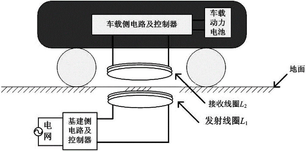
[0030] figure 1 The construction plan diagram of the electric vehicle magnetic resonance wireless charging circuit of the present invention is given, wherein the infrastructure side and the vehicle side are separated, the infrastructure side is installed under the ground, and the transmitting coil L 1 Close to the ground, when the receiving coil L on the vehicle side 2 in the transmitting coil L 1 When up, wireless charging is possible.

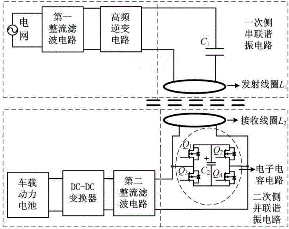
[0031] figure 2 The overall structure diagram of magnetic resonance wireless charging for electric vehicles is given. The infrastructure side includes the first rectification and filtering circuit, high-frequency inverter circuit and primary side series resonant circuit; the vehicle side includes the secondary side parallel resonant circuit, the second rectification and filteri...


PUM


Abstract

The invention discloses a magnetic resonance type wireless charging circuit of an electric automobile. The magnetic resonance type wireless charging circuit comprises an infrastructure side part and a vehicle-mounted side part, wherein the infrastructure side part comprises a first rectifying and filtering circuit, a high-frequency inverting circuit and a primary side series resonance circuit which are connected in sequence; the primary side series resonance circuit comprises a transmitting coil L1 and an alternating-current capacitor C1 which are connected in series; the first rectifying and filtering circuit is connected with a power grid; the vehicle-mounted side part comprises a secondary side parallel resonance circuit, a second rectifying and filtering circuit and a DC-DC (Direct Current-Direct Current) converter which are connected in sequence; the secondary side parallel resonance circuit comprises a receiving coil L2 and an electronic capacitive circuit which are connected in parallel; and the DC-DC converter is connected with a vehicle-mounted power battery. According to the circuit disclosed by the invention, magnetic resonance type wireless transmission is realized by adjusting the electronic capacitive circuit of the vehicle-mounted side part; and a communication function is not needed, the transmission efficiency is high, and thus the magnetic resonance type wireless charging circuit can be applied to the field of wireless charging of the electric automobile.

Description

technical field [0001] The invention relates to the field of electric vehicles, in particular to a magnetic resonance wireless charging circuit for electric vehicles and a control method thereof. Background technique [0002] In recent years, with the rapid increase in the number of electric vehicles in the world, the demand for electric vehicle charging equipment such as charging piles and charging stations has also increased. At present, the charging method of electric vehicles is mainly wired charging, but there are many wired charging methods. Disadvantages: The lead wire of the charging equipment is too long; the floor area and space occupied are large; the manual operation is cumbersome, and the operation process will cause excessive wear and unsafe problems of the equipment. The wireless charging technology for electric vehicles can well solve the above problems, and thus has received widespread attention. [0003] The current common wireless charging solutions for e...

Claims


Application Information

Patent Timeline
IPC IPC(8): H02J50/12H02J7/02B60L11/18
CPCH02J5/005H02J7/025B60L53/12Y02T10/72Y02T10/70Y02T10/7072Y02T90/14
Inventor 康龙云冯腾吴璟玥冯元彬王则沣
Owner SOUTH CHINA UNIV OF TECH
Why Eureka
Try Eureka