Device for detecting turbidity of pipe network end
A detection device and net tip technology, applied in measuring devices, color/spectral characteristic measurement, instruments, etc., can solve problems such as increased operating costs, achieve reduced operating costs, reduced maintenance workload, and small changes in water temperature
- Summary
- Abstract
- Description
- Claims
- Application Information
AI Technical Summary
Problems solved by technology
Method used
Image

Examples
Embodiment 1
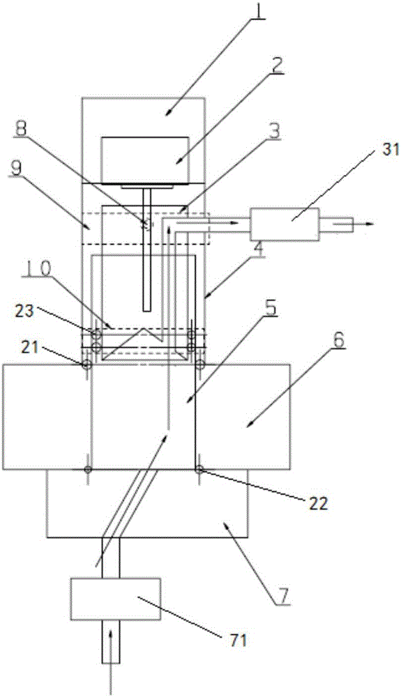
[0046] Such as figure 1 and figure 2 The present invention provides a turbidity detection device suitable for the end of the pipe network, including:
[0047] Housing 4, the housing 4 is a hollow columnar body,
[0048] A motor 2, the motor 2 is connected to the upper end of the housing 4,
[0049] A piston assembly, the piston assembly is arranged inside the housing 4; the piston assembly is connected to the motor 2;
[0050] A cuvette 5, the upper part of the cuvette 5 is located inside the housing 4, and the lower part of the piston assembly is sleeved in the cuvette 5;
[0051] The turbidity measurement part 6, the turbidity measurement part 6 is sleeved on the outer side of the lower part of the cuvette 5 and is sealed and connected with the lower part of the housing 4. The inside of the turbidity measurement part 6 is provided with an LED light source 11 and two light signals The detection device 12, the two optical signal detection devices 12 are respectively located...
Embodiment 2
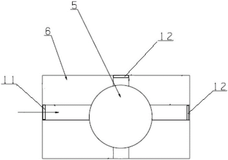
[0062] Such as figure 1 and image 3 As shown, the present invention provides a kind of turbidity detection device applicable to the end of pipe network, comprising:
[0063] Housing 4, the housing 4 is a hollow columnar body,
[0064] A motor 2, the motor 2 is connected above the casing 4,
[0065] A piston assembly, the piston assembly is arranged inside the housing 4; the piston assembly is connected to the motor 2;
[0066] A cuvette 5, the upper part of the cuvette 5 is located inside the housing 4, and the lower part of the piston assembly is sleeved in the cuvette 5;
[0067] The turbidity measurement part 6, the turbidity measurement part 6 is sleeved on the outer side of the lower part of the cuvette 5 and is fixedly connected with the housing 4, and the inside of the turbidity measurement part 6 is provided with an LED light source 11 and two optical signal detection Device 12, the LED light source has two LED lamps, the illumination directions of the two LED lam...
Embodiment 3
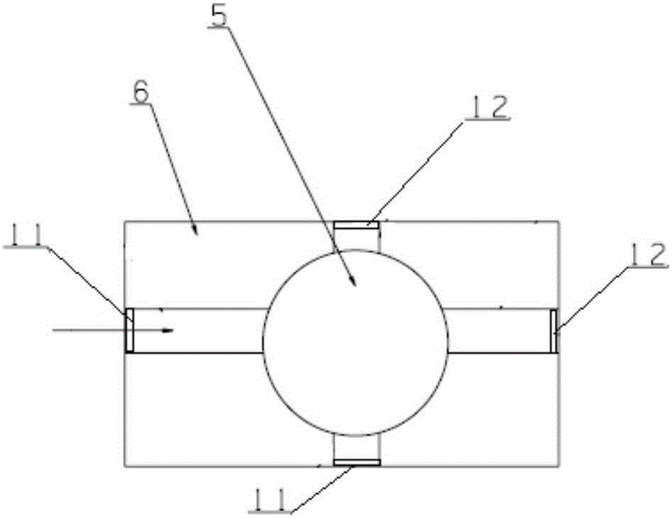
[0078] Such as figure 1 and Figure 4 As shown, the present invention provides a kind of turbidity detection device applicable to the end of pipe network, comprising:
[0079] Housing 4, the housing 4 is a hollow columnar body,
[0080] A motor 2, the motor 2 is connected above the casing 4,
[0081] A piston assembly, the piston assembly is arranged inside the housing 4; the piston assembly is connected to the motor 2;
[0082] A cuvette 5, the upper part of the cuvette 5 is located inside the housing 4, and the lower part of the piston assembly is sleeved in the cuvette 5;
[0083] The turbidity measurement part 6, the turbidity measurement part 6 is sleeved on the outer side of the lower part of the cuvette 5 and is fixedly connected with the housing 4, and the inside of the turbidity measurement part 6 is provided with an LED light source 11 and three optical signal detection Device 12, two of the three optical signal detection devices 12 are located in the 90° directi...
PUM
 Abstract
Description
Claims
Application Information
 - Generate Ideas
- Intellectual Property
- Life Sciences
- Materials
- Tech Scout
- Unparalleled Data Quality
- Higher Quality Content
- 60% Fewer Hallucinations
Browse by: Latest US Patents, China's latest patents, Technical Efficacy Thesaurus, Application Domain, Technology Topic, Popular Technical Reports.
© 2025 PatSnap. All rights reserved.Legal|Privacy policy|Modern Slavery Act Transparency Statement|Sitemap|About US| Contact US: help@patsnap.com