Multifunctional radiant tube combustion device

A technology of a combustion device and a radiant tube, applied in the directions of burners, combustion types, combustion methods, etc., can solve the problems of easy generation of local high temperature, consumption of high calorific value fuel, and high manufacturing cost, so as to improve the utilization rate of waste heat recovery of flue gas, improve the The effect of waste heat recovery rate and comprehensive investment cost reduction

Pending Publication Date: 2017-05-24
SHENWU TECH GRP CO LTD
View PDF5 Cites 1 Cited by
  • Summary
  • Abstract
  • Description
  • Claims
  • Application Information

AI Technical Summary

Problems solved by technology

The above various types of radiant tube technologies have been relatively mature, but each has certain limitations and deficiencies.
For the electric radiant tube, the load control is free, but it consumes high-grade energy, the cost is high, and it is not suitable for industrialization; the conventional gas radiant tube, the load control is free, the combustion is stable, but the fuel with high calorific value is consumed, and the exhaust gas temperature is high (the exhaust gas temperature is temperature of combustion flue gas), low thermal efficiency, easy to generate local high temperature, high uneven surface temperature of radiant tube, and excessive nitrogen oxides; self-preheating burner, complex structure inside radiant tube, prone to failure, high manufacturing cost , the air preheating temperature is limited, and the exhaust gas temperature is still not lower than 500°C; the regenerative radiant tube solves the problem of high exhaust gas temperature and the problem of high surface unevenness of the radiant tube, but when using low calorific value gas such as When blast furnace gas is used, the heating temperature range is limited. When it is lower than 650°C, the safety of use is threatened. High calorific value gas must be used as an eternal flame, which increases the instability of the system. Simple porous medium radiant tube combustion There is still a certain gap between the nitrogen oxides in the flue gas emitted by the device and the ultra-low emission

Method used


Image

  • Multifunctional radiant tube combustion device

Examples


Embodiment Construction

[0017] In order to enable those skilled in the art to better understand the technical solutions of the present invention, the present invention will be further described in detail below in conjunction with specific examples. The embodiments described below are exemplary only for explaining the present invention and should not be construed as limiting the present invention. If no specific technique or condition is indicated in the examples, it shall be carried out according to the technique or condition described in the literature in this field or according to the product specification.

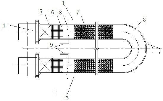
[0018] The present invention proposes a multifunctional radiant tube combustion device, figure 1 It is a structural schematic diagram of a multifunctional radiant tube combustion device of the present invention. According to an embodiment of the present invention, refer to figure 1 As shown, the device of the present invention includes: A-side combustion radiant tube 1, B-side combustion radi...


PUM


Abstract

The invention belongs to the field of combustion equipment and particularly relates to a multifunctional radiant tube combustion device, comprising a side A combustion radiant tube, a side B combustion radiant tube and a transitional radiant tube, wherein two ends of the transitional radiant tube are connected to one ends of the side A combustion radiant tube and the side B combustion radiant tube respectively, and the other end of the side A combustion radiant tube is sequentially provided with an air/fuel gas mixed gas inlet or a smoke outlet, a low-temperature heat accumulator, a denitration catalyst area and a porous medium layer area. The multifunctional radiant tube combustion device has the advantages that smoke discharge temperature can be decreased effectively, smoke waste heat recycling rate is increased, energy-saving effect is significant, smoke denitration measures are applied to the radiant tube combustion device, denitration and energy conservation are integrated, nitrogen oxide emission from smoke is reduced effectively, the system is more environmentally friendly, and comprehensive input cost is lowered.

Description

technical field [0001] The invention belongs to the field of combustion equipment, and in particular relates to a multifunctional radiant tube combustion device. Background technique [0002] The current types of radiant tubes include electric radiant tubes, conventional gas radiant tubes, self-preheating radiant tubes, regenerative radiant tubes, and various types of radiant tubes evolved from these basic forms. The above various types of radiant tube technologies are relatively mature, but each has certain limitations and deficiencies. For the electric radiant tube, the load control is free, but it consumes high-grade energy, the cost is high, and it is not suitable for industrialization; the conventional gas radiant tube, the load control is free, the combustion is stable, but the fuel with high calorific value is consumed, and the exhaust gas temperature is high (the exhaust gas temperature is temperature of combustion flue gas), low thermal efficiency, easy to generate...

Claims


Application Information

Patent Timeline
Patent Type & Authority Applications(China)
IPC IPC(8): F23D14/12F23D14/46F23J15/02F23D14/66F23D14/62F23J15/06
CPCF23D14/12F23D14/46F23D14/62F23D14/66F23J15/02F23J15/06Y02E20/30Y02E20/34
Inventor 吴道洪钟贵全郭科宏杨玉地宋敏洁
Owner SHENWU TECH GRP CO LTD
Why Eureka
Try Eureka