Spinneret plate and spinneret mechanism
A spinneret and spinneret technology, applied in textiles and papermaking, filament/thread forming, fiber processing, etc., can solve the problem of high cost, achieve the effect of reducing requirements and facilitating installation and disassembly
- Summary
- Abstract
- Description
- Claims
- Application Information
AI Technical Summary
Problems solved by technology
Method used
Image
Examples
Embodiment approach 1
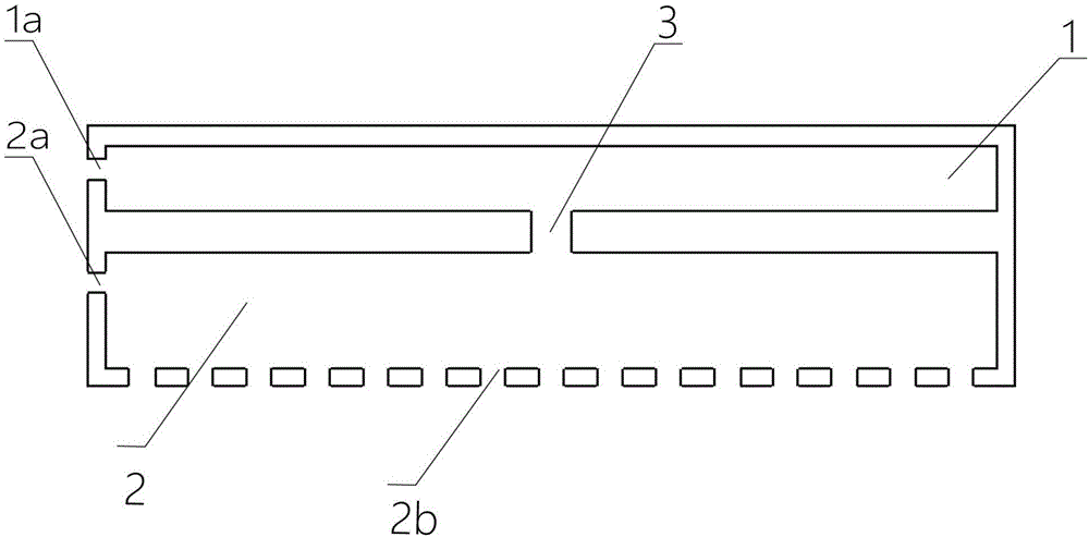
[0032] The first embodiment of the present invention provides a spinneret for use in electrospinning equipment, see figure 1 As shown, including the body, two layers of cavities are formed from top to bottom in the body, namely a gas cavity 1 and a liquid cavity 2. The gas cavity 1 is provided with a gas inlet 1a, and the liquid cavity 2 is provided with a liquid inlet 2a. ;
[0033] The gas cavity 1 and the liquid cavity 2 are connected by a one-way channel 3, and the liquid cavity 2 is in communication with a spinneret hole 2b provided at the bottom of the body;
[0034] The spinning liquid enters the liquid cavity 2 from the liquid inlet 2a, and the gas enters the gas cavity 1 from the gas inlet 1a, passes through the one-way channel 3 and enters the liquid cavity 2, pushing the spinning liquid to be ejected from the spinning hole 2b.
[0035] Among them, the one-way channel 3 can be constituted by setting a one-way valve, or can be constituted by controlling the pressure in the g...
Embodiment approach 2
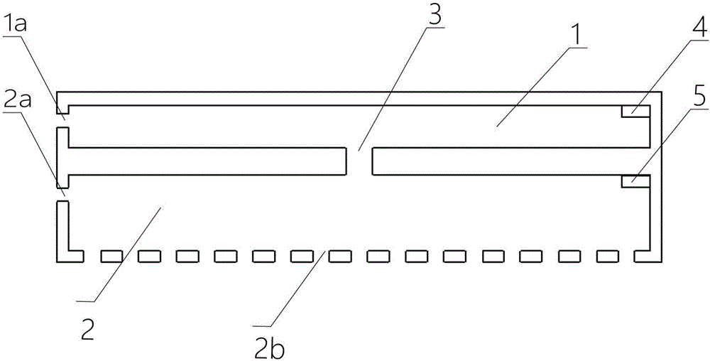
[0039] The second embodiment of the present invention provides a spinneret. The second embodiment is a further improvement of the first embodiment. The main improvement lies in that, in the second embodiment of the present invention, see figure 2 As shown, an air pressure sensor 4 is provided in the gas cavity 1 and a hydraulic sensor 5 is provided in the liquid cavity 2.
[0040] The air pressure sensor 4 and the hydraulic pressure sensor 5 are provided to monitor the fluid pressure in the gas cavity 1 and the liquid cavity 2 in real time to ensure the orderly progress of the production process.
Embodiment approach 3
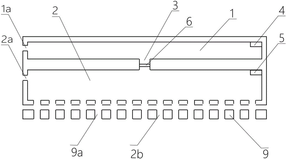
[0042] The third embodiment of the present invention provides a spinneret. The third embodiment is different from the first and second embodiments. The main difference is that in the first and second embodiments of the present invention, The one-way passage 3 is constituted by setting a one-way valve; and, in the third embodiment of the present invention, see image 3 As shown, an electronic valve 6 is provided in the one-way channel 3, and the electronic valve 6 is in communication connection with the air pressure sensor 4 and the hydraulic pressure sensor 5.
[0043] The electronic valve 6 opens when it detects that the gas pressure is stronger than the liquid pressure, and closes when it detects that the liquid pressure is stronger than the gas pressure. The automatic control of the electronic valve 6 ensures that the one-way channel 3 is in the passage state only when the gas pressure is stronger than the liquid pressure, which can more effectively prevent the spinneret from b...
PUM
 Abstract
Description
Claims
Application Information
 - R&D
- Intellectual Property
- Life Sciences
- Materials
- Tech Scout
- Unparalleled Data Quality
- Higher Quality Content
- 60% Fewer Hallucinations
Browse by: Latest US Patents, China's latest patents, Technical Efficacy Thesaurus, Application Domain, Technology Topic, Popular Technical Reports.
© 2025 PatSnap. All rights reserved.Legal|Privacy policy|Modern Slavery Act Transparency Statement|Sitemap|About US| Contact US: help@patsnap.com


