
Ink brush container

A brush and pen holder technology, applied in the field of stationery, can solve the problems of not being able to clean the ink, affecting reuse, and time-consuming and laborious cleaning of the brush.

Inactive Publication Date: 2017-05-24
浙江八瓦文化创意发展有限公司
View PDF13 Cites 8 Cited by
  • Summary
  • Abstract
  • Description
  • Claims
  • Application Information

AI Technical Summary

Problems solved by technology

[0002] The brush is a traditional writing tool that originated in China, and it is also a painting tool; it is usually placed in a pen holder, which is a special utensil for holding a brush. Although it is not included in the four treasures of the brush, ink, paper and inkstone, it is still common It is preferred by literati; and washing the brush is a very time-consuming and laborious thing. If the brush is not cleaned after use, it will affect its reuse and shorten the service life of the brush; and with the development of human society and the advancement of technology, Existing brush holders can no longer meet people's needs, and multifunctional brush holders are needed
[0003] Nowadays, the brush holder for automatic brush cleaning is generally to lock the brush and hang it in the brush holder, then put water in the holder, and then use the motor to clean the brush in circles, or use a convection device to impact and scrub the inner of the brush, but in this way Using centrifugal force or the convective impact of water to clean the brush can not completely clean the ink in the brush tank. If there is too much ink in the brush, there will be a lot of ink remaining in the brush tank, and the brush cannot be completely cleaned, which will affect the use of the brush. life

Method used


Image

  • Ink brush container
  • Ink brush container
  • Ink brush container

Examples


Embodiment Construction

[0013] The present invention will be further described below in conjunction with the accompanying drawings and specific embodiments.

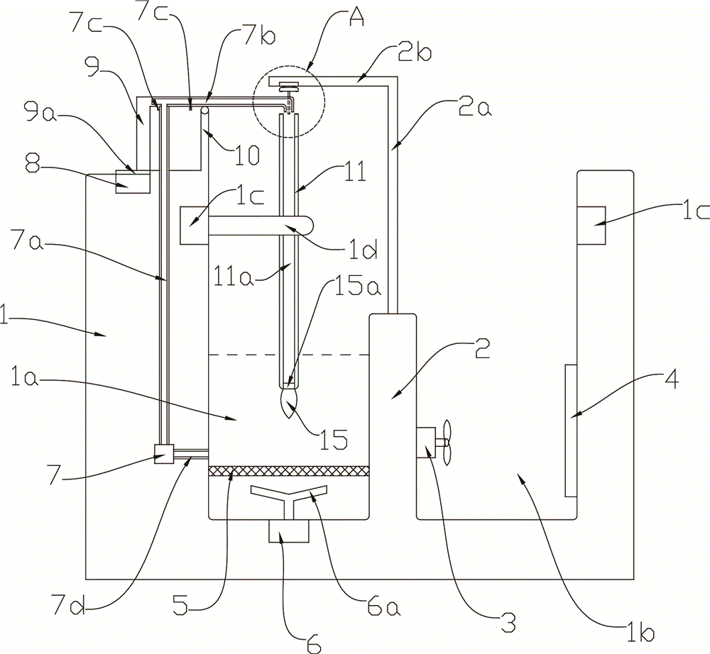
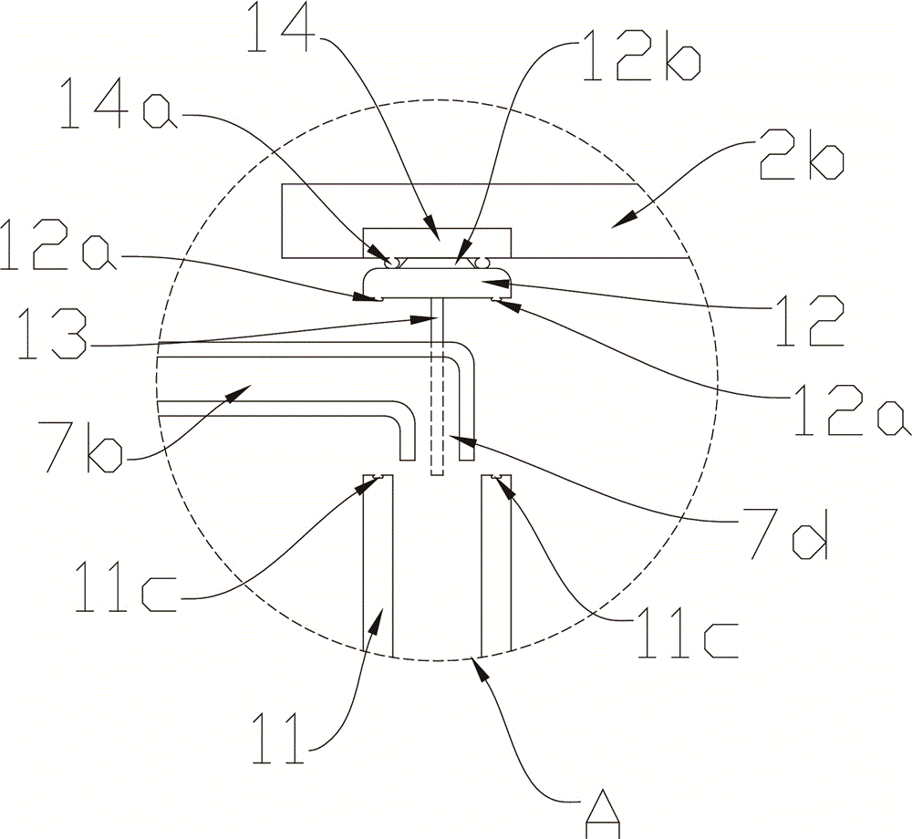
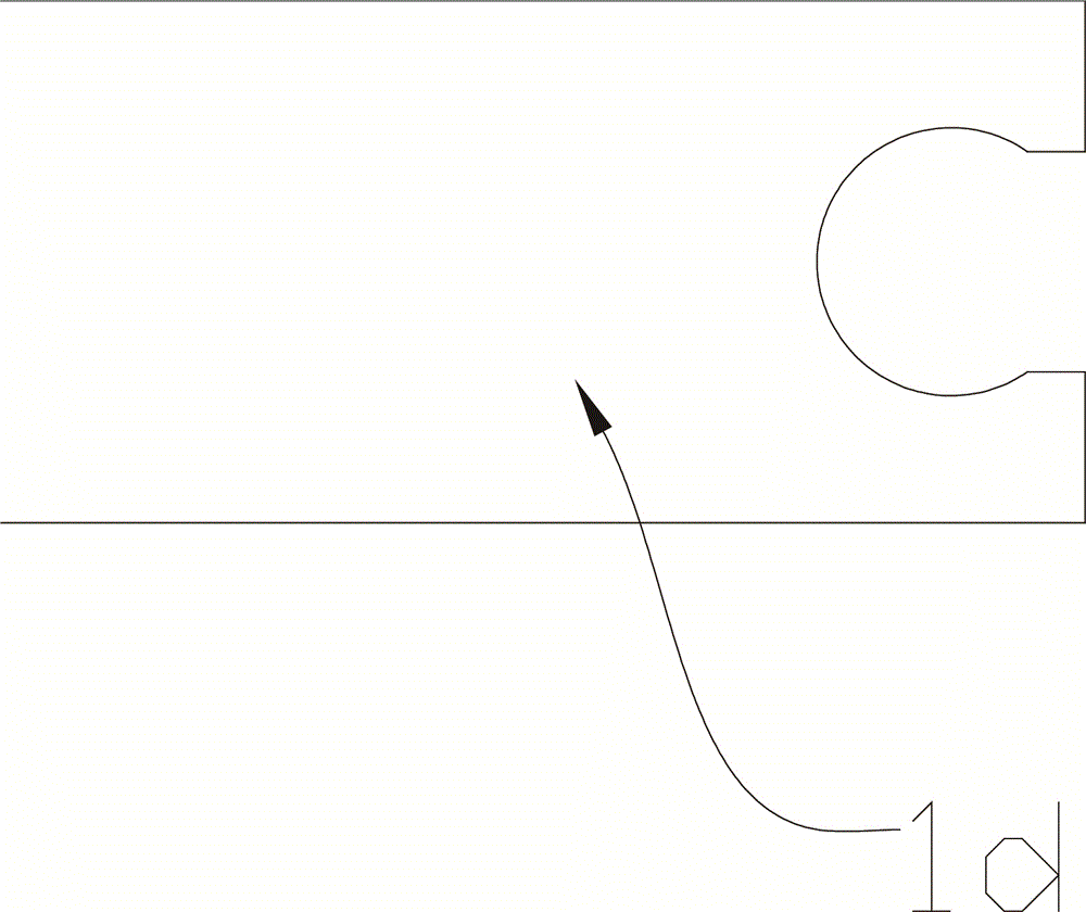
[0014] See Figure 1 to Figure 4 , a kind of writing brush holder, is used for cleaning the writing brush that the tip of pen holder 11 can be opened and is hollow; Comprising cylinder body 1 and the partition plate 2 that is arranged in cylinder body 1, described partition plate 2 separates cylinder body 1 into cleaning area 1a and In the drying area 1b, a filter screen 5 is arranged under the cleaning area 1a, and a first motor 6 is arranged in the bottom of the cylinder body 1 of the cleaning area 1a under the filter screen 5, and the first motor 6 is connected with a The upwardly inclined fan blade 6a is used to rotate the water flow; the side wall of the cylinder 1 is provided with an annular track 1c, and the first clamping rod 1d is connected to the annular track 1c, and the inner wall of the cleaning area 1a on the filter screen 5 A fi...


PUM


Abstract

The invention discloses an ink brush container which is characterized in that an electromagnet arranged below a bending rod attracts an iron sheet on a penholder top end cover to pull out the penholder top end cover, then a pushing and pulling device pushes a pushing block to move, a water inlet of a third water conveying channel connected with the pushing block is communicated with a water outlet in the end part of a second water conveying channel through a baffle, the water outlet of the third water conveying channel is pushed to move to the part below the opened penholder top end cover, and the water outlet of the third water conveying channel to be aligned with the hollow part of a penholder; therefore, water in a cleaning area can flow into the hollow part of the penholder from the water conveying channels through pumping equipment and can further flow into the ink bag of the ink brush head through a grid plate on which the ink brush head is fixed, meanwhile, a first motor drives upward inclined blades to rotate the water flow to generate a certain centrifugal force, and at the moment, the water flow entering the ink bag of the ink brush head flows out to take ink away from the ink bag, ink can be transferred away by rotation through the centrifugal force generated by the rotational water flow, so that ink in the ink bag can be cleared out from the inner part of the ink bag, and the ink brush can be cleaned thoroughly.

Description

technical field [0001] The invention relates to the field of stationery, in particular to a brush holder. Background technique [0002] The brush is a traditional writing tool that originated in China, and it is also a painting tool; it is usually placed in a pen holder, which is a special utensil for holding a brush. Although it is not included in the four treasures of the brush, ink, paper and inkstone, it is still common It is preferred by literati; and washing the brush is a very time-consuming and laborious thing. If the brush is not cleaned after use, it will affect its reuse and shorten the service life of the brush; and with the development of human society and the advancement of technology, Existing brush holders can no longer satisfy people's needs, and multifunctional brush holders are needed. [0003] Nowadays, the brush holder for automatic brush cleaning is generally to lock the brush and hang it in the brush holder, then put water in the holder, and then use ...

Claims


Application Information

Patent Timeline
Patent Type & Authority Applications(China)
IPC IPC(8): B43K13/02
CPCB43K13/02
Inventor 唐一田
Owner 浙江八瓦文化创意发展有限公司
Learn More