
A passive dynamic leveling control system of hydraulic press and its control method

A control system and hydraulic press technology, applied in the direction of presses, manufacturing tools, etc., can solve the problems of electro-hydraulic proportional dynamic leveling control system manufacturing, high maintenance costs, poor anti-interference ability, and difficult control

Active Publication Date: 2018-07-20
FUZHOU UNIV
View PDF6 Cites 0 Cited by
  • Summary
  • Abstract
  • Description
  • Claims
  • Application Information

AI Technical Summary

Problems solved by technology

[0006] (1) The manufacturing and maintenance costs of the electro-hydraulic proportional dynamic leveling control system are high
In the prior art, the electro-hydraulic proportional control system is mostly used for dynamic leveling of the movable beam of the press. Although it has high control accuracy, multi-axis controllers are often used in combination with proportional valves and proportional servo valves or multiple proportional valves are used. The structure of the leveling control system constitutes a leveling control system, which greatly increases the manufacturing cost of the hydraulic machine; or the proportional valve is used to directly control the return cylinder. Although the structure is simplified, the disadvantage of high manufacturing cost of the leveling control system cannot be avoided.
[0007] (2) The algorithm of the electro-hydraulic proportional dynamic leveling control system is complex and difficult to control
Most of the existing technologies use PID controllers and set virtual axis models to perform closed-loop control on four high-response proportional servo valves or proportional directional valves, and then perform closed-loop control on four leveling hydraulic cylinders or return cylinders to achieve passive adjustment. However, in the process of actual press commissioning and maintenance, it is necessary to select the key setting parameter proportional gain K of the PID controller according to the experience of the engineer. P , integral gain K I , differential gain K D , and further carry out more complicated debugging, so as to obtain the key setting parameters of the PID controller suitable for the press under actual working conditions, which greatly increases the time and difficulty of debugging and maintenance, and increases the cost of production and maintenance
[0008] (3) The anti-interference ability of the electro-hydraulic proportional dynamic leveling control system is poor, and the design of the electrical system is difficult
In the prior art, the form of analog signal output is mostly used to control the displacement of the proportional valve or servo valve spool, and then realize the dynamic leveling control of the four leveling hydraulic cylinders or return cylinders. However, due to the analog output form Its own characteristics make its required hardware requirements and environmental requirements higher, making the design of the electrical system more difficult, and its anti-interference ability is poor, and the probability of being affected by complex environments in actual working conditions is greatly increased, thereby reducing the entire electrical system. Stability and applicability of liquid control system

Method used


Image

  • A passive dynamic leveling control system of hydraulic press and its control method
  • A passive dynamic leveling control system of hydraulic press and its control method
  • A passive dynamic leveling control system of hydraulic press and its control method

Examples


Embodiment Construction

[0055] The present invention will be further described below in conjunction with the accompanying drawings and specific embodiments.

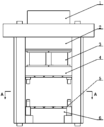
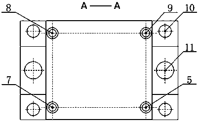
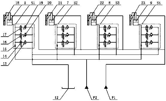
[0056] Such as image 3 As shown, a passive dynamic leveling control system of a hydraulic machine in this embodiment, the hydraulic machine body includes a main system oil tank 1, an upper beam 2, a master cylinder 3, a first leveling hydraulic cylinder 5, and a second leveling hydraulic cylinder 7. The third leveling hydraulic cylinder 8, the fourth leveling hydraulic cylinder 9, the return cylinder 11, the movable beam 4 and the lower beam 6, the main system oil tank 1 is installed on the upper end of the upper beam 2, and the main cylinder 3 and the return cylinder 11 are composed of The main system controls and jointly drives the movable beam 4 to realize reciprocating motion between the upper beam 2 and the lower beam 6, the first leveling hydraulic cylinder 5, the second leveling hydraulic cylinder 7, the third leveling hydraulic cylinde...


PUM


Abstract

The invention relates to a passive type dynamic levelling control system of a hydraulic machine. The system comprises a controller, a constant-pressure oil source P1, a high-pressure oil source P2, an oil tank, a first displacement sensor, a second displacement sensor, a third displacement sensor, a fourth displacement sensor, a first dynamic levelling hydraulic sub-system S1, a second dynamic levelling hydraulic sub-system S2, a third dynamic levelling hydraulic sub-system S3, and a fourth dynamic levelling hydraulic sub-system S4, wherein each of the first, the second, the third and the fourth dynamic levelling hydraulic sub-systems is composed of a first check valve, a first, a second and a third electromagnetic ball valves, and a first, a second and a third levelling overflow valves; the oil inlets of the first, the second and the third electromagnetic ball valves are communicated with each other and connected with a rodless cavity of a first levelling hydraulic cylinder; the oil outlets of the first, the second and the third electromagnetic ball valves are respectively connected with the oil inlets of the first, the second and the third levelling overflow valves; and the oil outlets of the first, the second and the third leveling overflow valves are communicated with each other and connected back to the oil tank. The passive type dynamic levelling control system provided by the invention has the advantages that the antijamming capability is high and the stability is high.

Description

technical field [0001] The invention relates to a hydraulic control system, in particular to a passive dynamic leveling control system of a hydraulic machine and a control method thereof. Background technique [0002] The dynamic leveling control system of the movable beam of the hydraulic press is widely used in metal die forging forming equipment, metal stretch forming equipment and composite material compression forming equipment. The application of the dynamic leveling control system of the movable beam of the hydraulic press can significantly improve the precision of the workpiece, reduce the wear of the mold, and prolong the life of the press. It has become one of the key technologies to measure the manufacturing level of the hydraulic press. The breakthrough and improvement of related technologies have important significance. [0003] At present, the design of the dynamic leveling control system of the hydraulic press mainly revolves around the following two aspects:...

Claims


Application Information

Patent Timeline
Patent Type & Authority Patents(China)
IPC IPC(8): B30B15/16
CPCB30B15/16B30B15/166
Inventor 杜恒张玻溶蔡文杰陈淑梅陈晖
Owner FUZHOU UNIV
Learn More