Organic electroluminescent element
An electroluminescent device and luminescent technology, applied in the direction of electric solid-state devices, electrical components, luminescent materials, etc., can solve the problems of high luminous efficiency, insufficient improved characteristics, low driving voltage, etc.
- Summary
- Abstract
- Description
- Claims
- Application Information
AI Technical Summary
Problems solved by technology
Method used
Image
Examples
example
[0358] 4,4’,4”-tris(N-carbazolyl)triphenylamine (TCTA);
[0359] 9,9-bis[4-(carbazol-9-yl)phenyl]fluorene;
[0360] 1,3-bis(carbazol-9-yl)benzene (mCP); and
[0361] 2,2-Bis(4-carbazol-9-ylphenyl)adamantane (Ad-Cz).
[0362] In addition to the above-mentioned carbazole derivatives, represented by 9-[4-(carbazol-9-yl)phenyl]-9-[4-(triphenylsilyl)phenyl]-9H-fluorene in A compound having a triphenylsilyl group in the molecule and having a triarylamine skeleton can also be used as a material for electron blocking layer formation.
[0363] Hole blocking layer:
[0364] The hole blocking layer despite the figure 1 is not shown in , but is optionally provided between the electron transport layer and the light-emitting layer, and is formed to block the penetration of holes from the light-emitting layer to improve luminous efficiency. Compounds with a hole-blocking function, such as phenanthroline derivatives such as bathocuproine (BCP), such as bis(2-methyl-8-hydroxyquinolinat...
Embodiment 1
[0407]
[0408] (first step)
[0409] To a nitrogen purged reaction vessel was added
[0410]
[0411] While the mixture was irradiated with ultrasonic waves for 30 minutes, nitrogen gas was passed therethrough.
[0412] Then, add palladium acetate 0.54g and
[0413] 50% (w / v) toluene solution of tert-butylphosphine 1.46g
[0414] The mixture was heated and stirred at 95°C for 4 hours.
[0415] After removing insoluble matter by filtration, the filtrate was heated, and subjected to adsorption purification using silica gel at 100° C., followed by hot filtration. The filtrate was cooled to room temperature under stirring, and the precipitated solid was collected by filtration, thereby obtaining 50.2 g (yield 88%) of N,N-bis(biphenyl-4-yl)-N-( biphenyl-3-yl)amine.
[0416] (second step)
[0417] To a nitrogen purged reaction vessel was added
[0418] 50.0 g of the triarylamine obtained above, and
[0419] Dimethylformamide 500mL,
[0420] And the mixture was cooled ...
Embodiment 2
[0441]
[0442] The reaction was performed under the same conditions as in Example 1 except that phenylboronic acid used in the third step of Example 1 was replaced by 1-naphthylboronic acid. As a result, the following products were obtained:
[0443] 9.2 g (61% yield) of N,N-bis(biphenyl-4-yl)-N-{6-(naphthyl-1-yl)biphenyl-3-yl}amine as a white powder.
[0444] The obtained amine compound is compound (1-2) represented by the following formula:
[0445]
[0446] pm-substituted benzene ring: 1
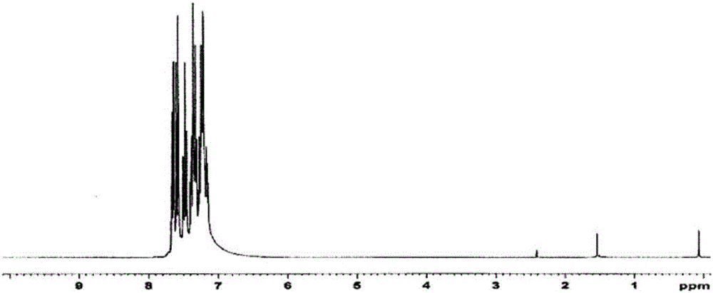
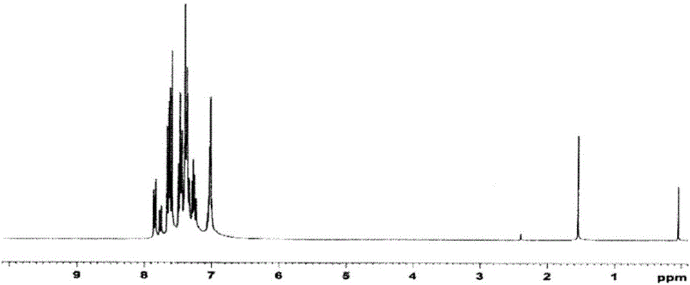
[0447] Regarding the white powder obtained above, its structure was identified using NMR. Its NMR chart is shown in image 3 .
[0448] exist 1 H-NMR (CDCl 3 ), the following 33 hydrogen signals were detected:
[0449] δ(ppm)=7.84-7.87(3H)
[0450] 7.67-7.83(6H)
[0451] 7.26-7.64(18H)
[0452] 7.02-7.04(6H)
PUM
| Property | Measurement | Unit |
|---|---|---|
| glass transition temperature | aaaaa | aaaaa |
| glass transition temperature | aaaaa | aaaaa |
Abstract
Description
Claims
Application Information
 - R&D
- Intellectual Property
- Life Sciences
- Materials
- Tech Scout
- Unparalleled Data Quality
- Higher Quality Content
- 60% Fewer Hallucinations
Browse by: Latest US Patents, China's latest patents, Technical Efficacy Thesaurus, Application Domain, Technology Topic, Popular Technical Reports.
© 2025 PatSnap. All rights reserved.Legal|Privacy policy|Modern Slavery Act Transparency Statement|Sitemap|About US| Contact US: help@patsnap.com


