Mist eliminator

A droplet separator, droplet technology, applied in the direction of separation method, dispersed particle separation, membrane filter, etc.

Active Publication Date: 2017-05-17
GEA AIR TREATMENT
View PDF8 Cites 0 Cited by
  • Summary
  • Abstract
  • Description
  • Claims
  • Application Information

AI Technical Summary

Problems solved by technology

But this leads to additional space requirement

Method used


Image

  • Mist eliminator
  • Mist eliminator
  • Mist eliminator

Examples


Embodiment Construction

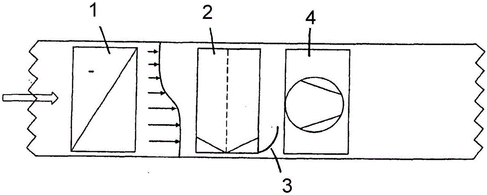
[0020] In the air flow generated by the fan / ventilator 4, downstream of the cooler 1 of the air-conditioning, cooling or ventilation system, there is a droplet separator 2 having a plurality of mutually parallel blades as a blade group, The vanes preferably each have a corrugated profile in cross section and are preferably surrounded by a frame. At least one baffle 3 is fixed obliquely in the air flow directly downstream of the vane group in such a way that the lower edge of the baffle is closer to the lower edge of the air-conditioning or cooling device than the upper edge. Preferably the lower edge is fastened to the lower part of the device.

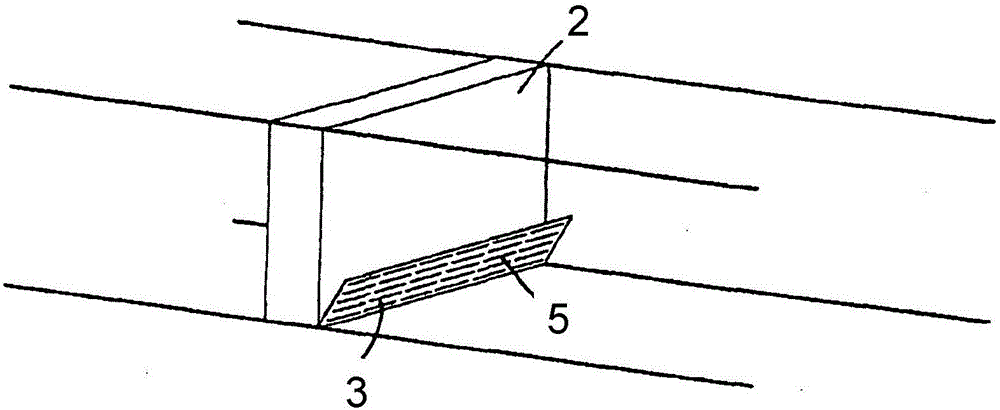
[0021] The baffle 3 is preferably as figure 1 have a flat shape as shown or as figure 2 The shown has a concavely curved shape and in one embodiment has a plurality of openings 5 ​​distributed evenly over the surface of the baffle. The baffle is thus preferably formed from a sieve plate or from a sieve plate-like metal plate. A p...


PUM


Abstract

The invention relates to a device for separating drops from the air flow after an air-conditioning, cooling, and/or ventilation device, comprising a plurality of drop-catching fins, which are arranged parallel to each other and between which the air flows. A baffle plate is arranged directly after the mist eliminator, in particular the fins thereof, in the flow direction. The drops of the air flow hit the baffle plate in order to slide downward on the baffle plate.

Description

technical field [0001] The invention relates to a device for separating liquid droplets from an air stream downstream of an air conditioner, cooling device and / or ventilation device, comprising a plurality of vanes arranged parallel to one another to catch the liquid droplets, between which air flows . Background technique [0002] In known droplet separators, the vanes which catch the droplets are located in a grouped layer arranged transversely to the air flow. In such organized layers it has been shown that not all droplets can be captured. This is because air-based temperature stratification creates a temperature distribution on the separator after the cooler. This temperature distribution leads to recondensation on the rear side of the separator, in particular on the rear side of the blades, by heat conduction in the blades. The liquid droplets condensed there are entrained by the air flow. [0003] Furthermore, those droplets not caught by the droplet separator hav...

Claims


Application Information

Patent Timeline
IPC IPC(8): B01D45/08
CPCB01D45/08B01D2279/50
Inventor C·菲伯格
Owner GEA AIR TREATMENT
Why Eureka
Try Eureka