Protective circuit used in starting and operating processes of single-phase asynchronous motor
An operation process, single-phase asynchronous technology, applied in the direction of emergency protection circuit devices, emergency protection circuit devices, circuit devices, etc. for limiting overcurrent/overvoltage, can solve problems such as large current and motor failure to start, and achieve contact The effect of small resistance, simple circuit and reliable shunt
- Summary
- Abstract
- Description
- Claims
- Application Information
AI Technical Summary
Problems solved by technology
Method used
Image
Examples
Embodiment 1
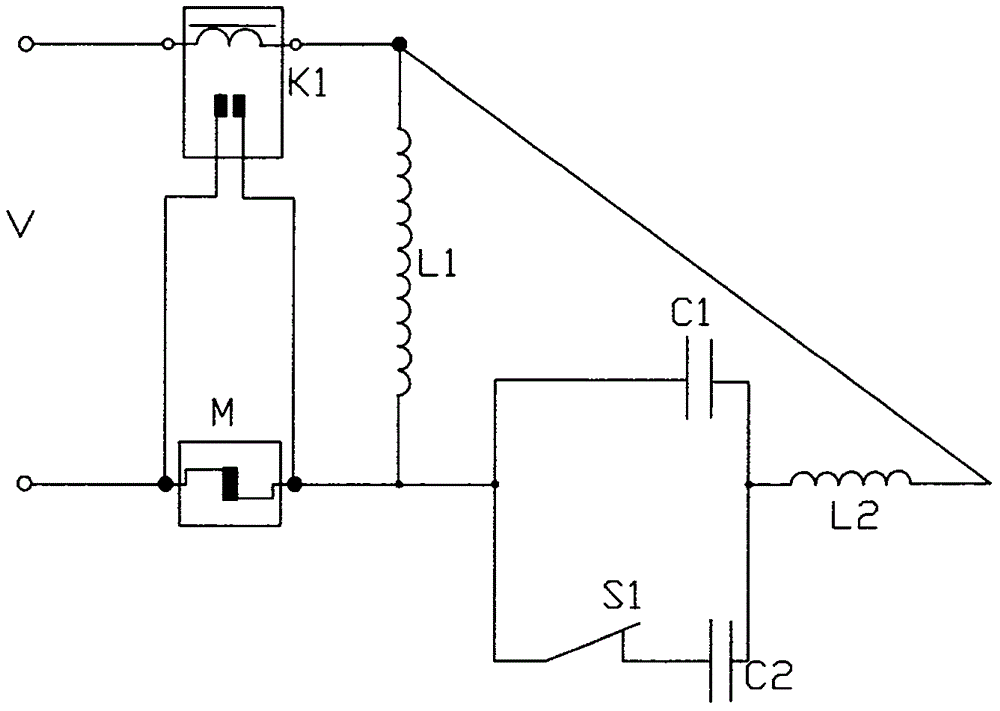
[0021] Such as figure 2 As shown, the current relay K1, the main winding L1, the overcurrent protector M, and the power supply V are connected in series in sequence; the loop composed of the running capacitor C1, the starting capacitor C2, and the centrifugal switch S1 is connected in parallel with the secondary winding L2 after being connected in series. On L1; the contacts of the current relay K1 are connected with the contacts of the overcurrent protector M.
[0022] The current relay contact is in the normally open state when the power switch is turned off; when the power is turned on and a large current is applied, the magnetic field generated attracts the moving contact and the fixed contact to close and is connected in parallel with the overcurrent protector contact to prevent overcurrent The protector acts as a shunt to ensure that the overcurrent protector passes a small amount of current during the starting process of the motor without power failure; after starting,...
Embodiment 2
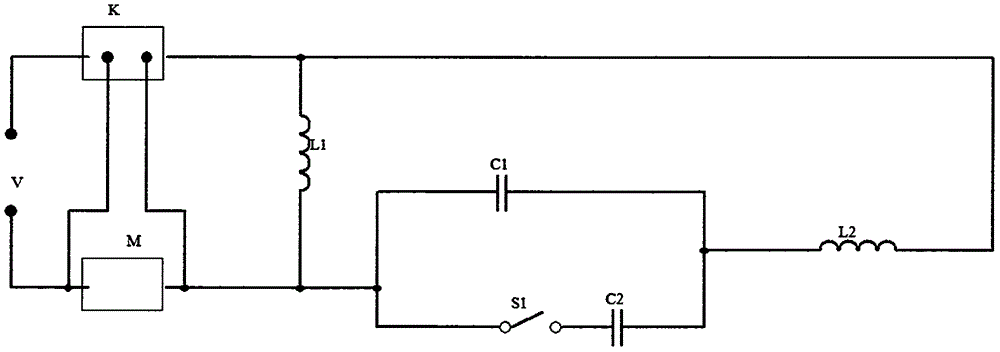
[0024] Such as image 3 As shown, the main winding L1, the overcurrent protector M, and the power supply V are connected in series in sequence; the circuit composed of the running capacitor C1, the starting capacitor C2, and the centrifugal switch S1 is connected in parallel with the secondary winding L2 after being connected in series with the main winding L1; bistable The contacts of the relay K2 are connected to the contacts of the overcurrent protector M, the combination of the bistable relay K2 and the electronic controller N is connected in parallel at both ends of the dual-state centrifugal switch S2, and the input terminal of the electronic controller N is connected to on the output of the two-state switch S2.
[0025] The polarity of the permanent magnetic field installed at one end of the movable contact in the bistable relay and the positive and negative polarities connected to the two lead-out wires of the trigger coil determine that the two contacts are closed und...
Embodiment 3
[0027] Such as Figure 4 As shown, the main winding L1, the overcurrent protector M, and the power supply V are connected in series in sequence; the circuit composed of the operating capacitor C1, the starting capacitor C2, and the centrifugal switch S1 is connected in parallel with the secondary winding L2 after being connected in series. On L1; the contacts of the solid state relay K3 are connected to the contacts of the overcurrent protector M; the solid state relay K3 is connected in parallel at both ends of the centrifugal switch S1.
[0028] Use the opening and closing state of the centrifugal switch contact as the trigger signal of the SCR in the solid state relay to control the conduction and cut-off of the SCR in the solid state relay K3. When the motor is in the starting state, the SCR is turned on, and the two ends of the SCR It is connected in parallel with the overcurrent protector to act as a shunt; the motor is started, the centrifugal switch is disconnected, th...
PUM
 Abstract
Description
Claims
Application Information
 - R&D Engineer
- R&D Manager
- IP Professional
- Industry Leading Data Capabilities
- Powerful AI technology
- Patent DNA Extraction
Browse by: Latest US Patents, China's latest patents, Technical Efficacy Thesaurus, Application Domain, Technology Topic, Popular Technical Reports.
© 2024 PatSnap. All rights reserved.Legal|Privacy policy|Modern Slavery Act Transparency Statement|Sitemap|About US| Contact US: help@patsnap.com


