
A negative ion generator used in a large space

A negative ion generator, large space technology, applied in electrical components and other directions, can solve the problems of large negative ion release, decreased negative ion release, low pulse current operating frequency, etc., achieves large negative ion release, increased penetration distance, guaranteed Smooth running effect

Active Publication Date: 2018-01-23
玛雅森林(北京)国际科技有限公司
View PDF4 Cites 0 Cited by
  • Summary
  • Abstract
  • Description
  • Claims
  • Application Information

AI Technical Summary

Problems solved by technology

[0003] In order to overcome the existing small anion generator, due to the limitation of its structure, it releases large particle size anions when working, the power is small, the amount of anion release is small, and the radius of anion ejection is short. A large area provides sufficient amount of negative ions; and the existing high-power negative ion generator, because the thyristor is used as the core component to generate pulse current, and the pulse current generated by the thyristor as the core component has a low operating frequency, which causes the subsequent circuit to release negative ions. , the emission distance of negative ions is short, the penetration distance is short, and it is easy to generate high temperature during work, which leads to the disadvantages of a large decrease in the release of negative ions. function, generate high-frequency pulses, and under the action of related circuits, the penetration distance of negative ions generated by subsequent circuits will be greatly increased. The working power is large, the amount of negative ions released is large, and the radius of negative ion projection is long. It can continuously release high-concentration small-size negative ions, which can meet A negative ion generator used in large spaces (such as unit offices and classrooms)

Method used


Image

  • A negative ion generator used in a large space
  • A negative ion generator used in a large space
  • A negative ion generator used in a large space

Examples


Embodiment Construction

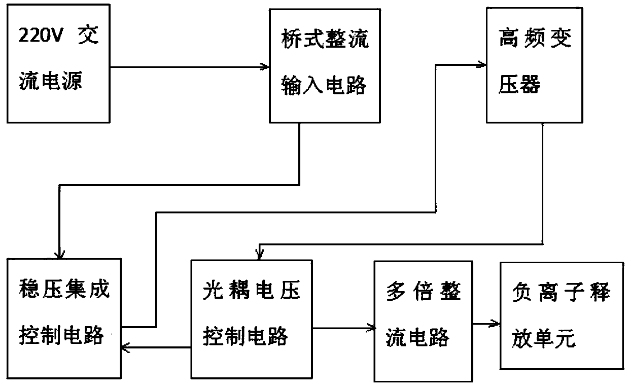
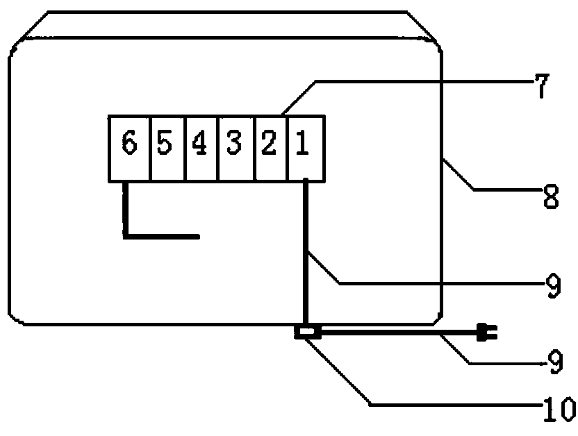
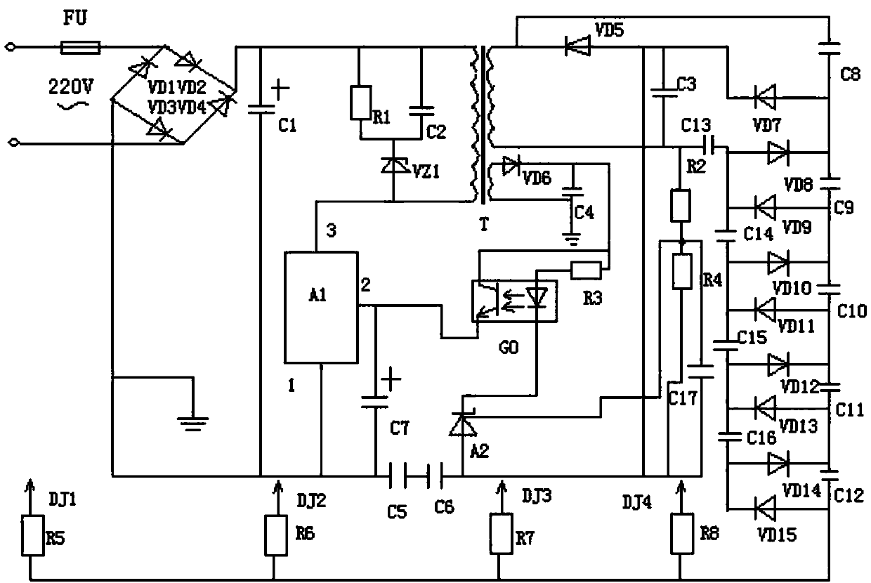
[0016] Depend on figure 1 , figure 2 As shown in , a negative ion generator used in a large space is composed of a bridge rectifier input circuit 1, a voltage stabilizing integrated control circuit 2, a high frequency transformer 3, an optocoupler voltage control circuit 4, a multiple rectification circuit 5, and an anion releasing unit 6. The generator casing 7 and the body casing 8 are composed. The bridge rectification input circuit 1 power input terminal and the 220V AC power supply are connected by wires. The bridge rectification input circuit 1 positive power output terminal and the voltage stabilization integrated control circuit 2 positive power supply input terminal One end of the primary winding of the high-frequency transformer 3 is connected by a wire, the output end of the power supply of the integrated control circuit 2 and the other end of the primary winding of the high-frequency transformer 3 are connected by a wire, and the first and second output ends of th...


PUM


Abstract

An anion generator used in large space comprises a bridge rectification input circuit, a voltage-stabilizing integrated control circuit, a high-frequency transformer, an optocoupler voltage control circuit, a voltage-multiplying rectifier circuit, an anion release unit, a generator shell and a machine body shell. The bridge rectification input circuit, the voltage-stabilizing integrated control circuit, the high-frequency transformer, the optocoupler voltage control circuit, the voltage-multiplying rectifier circuit and the anion release unit are connected through wires and installed in the generator shell, and the generator shell is installed in the machine body shell. Due to combined action of the voltage-stabilizing integrated control circuit, the high-frequency transformer and the optocoupler voltage control circuit, stable and continuous high-frequency pulses are generated, the penetration distance of anions generated by follow-up circuits is greatly increased under the action of related circuits, work power is large, the anion release amount is large, the anion cast radius is long, high-concentration small-particle-size anions can be continuously released, and the anion generator can be used in large areas and space.

Description

technical field [0001] The invention relates to the field of electrical equipment, in particular to a device that can continuously release high-concentration and small-diameter negative ions during work, has high working power, large negative ion release volume, and long negative ion ejection radius, and can be used in areas with large spaces (such as unit offices, classrooms, etc.) ) is a negative ion generator used in a large space. Background technique [0002] At present, due to the limitation of its structure, the existing small negative ion generators generally release large particle size negative ions when working, the power is small, the amount of negative ions released is small, and the radius of negative ion projection is short. They are mainly used in places with small spaces such as homes and cars. use, it cannot be used normally in areas with large spaces (such as classrooms, unit offices), and cannot provide sufficient negative ions to areas with large spaces; ...

Claims


Application Information

Patent Timeline
Patent Type & Authority Patents(China)
IPC IPC(8): H01T23/00
CPCH01T23/00
Inventor 周丰怀
Owner 玛雅森林(北京)国际科技有限公司
Learn More