Solid laser quality improving method based on in-cavity phase conjugate

A solid-state laser, phase conjugation technology, applied in lasers, laser parts, lasers using scattering effects, etc., can solve the problems of high requirements on mirror materials, complex systems, and expensive adaptive optics systems.

Inactive Publication Date: 2017-05-17
DALIAN INST OF CHEM PHYSICS CHINESE ACAD OF SCI
View PDF2 Cites 2 Cited by
  • Summary
  • Abstract
  • Description
  • Claims
  • Application Information

AI Technical Summary

Problems solved by technology

The adaptive optics system is expensive and complex, and the mirror surface needs to withstand rapidly changing stress, which requires high requirements on the material of the mirror

Method used


Image

  • Solid laser quality improving method based on in-cavity phase conjugate
  • Solid laser quality improving method based on in-cavity phase conjugate
  • Solid laser quality improving method based on in-cavity phase conjugate

Examples


Embodiment 1

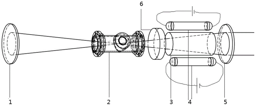
[0016] The device used in Example 1 is as figure 2 shown. Two f=1m spherical mirrors are used to form a concentric cavity with a distance of 1m. The rear cavity mirror marked 1 is specifically a silver-plated total reflection mirror, and the output coupling mirror marked 5 is specifically a half mirror with a coupling rate of 55%. Placed in the cavity from front to back are:

[0017] Two xenon lamps are used as pumping sources4.

[0018] Neodymium glass is used as the solid gain medium 3; its diameter is 10 mm, and its length is 9 cm; the Nd doping concentration is 1%.

[0019] A Fabry-Perot etalon with a thickness of 0.7 mm and a reflectance of 70% on both sides is used as the line width narrowing device 6 .

[0020] Brillouin medium gas pool as Brillouin medium 2. Stainless steel is used as the main material, fused silica is used as the window, and the interior is filled with SF 6 Or high-pressure gas such as perfluorocarbon; can be filled with appropriate buffer gas....

Embodiment 2

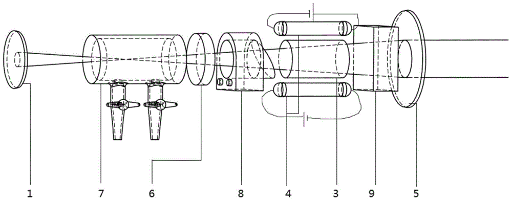
[0023] The schematic diagram of the device in Example 2 is attached image 3 shown. Two mirrors are used to form a real confocal cavity with a distance of 1.2m. The rear cavity mirror 1 is specifically a silver-plated high-reflection mirror with f=300mm, and the output coupling mirror 5 is specifically a coated mirror with f=900mm, HR@1064nm, and HT@532nm.

[0024] Inside the resonator from back to front are:

[0025] The liquid medium pool 7 is used as a Brillouin medium, filled with a Brillouin medium liquid such as CS 2 , CCl 4 Wait. The liquid in the pool can flow through the external pump through the two pistons.

[0026] A Fabry-Perot etalon with a thickness of 0.7 mm and a reflectance of 70% on both sides is used as the line width narrowing device 6 .

[0027] The Q switch 8 made of electro-optic crystal and Brewster window is used to form high peak power pulse laser.

[0028] Two xenon lamps are used as pumping sources4.

[0029] Nd-doped yttrium aluminum garne...


PUM

PropertyMeasurementUnit
Diameteraaaaaaaaaa
Lengthaaaaaaaaaa
Thicknessaaaaaaaaaa

Abstract

The invention provides a solid quality improving method based on in-cavity phase conjugate, and aims at solving problems that light beams of a solid state laser are severe in heat distortion and present active optical means are complex and expensive. The solid state laser with an optical phase conjugate cavity is provided, and solid laser of high light beam quality can be obtained. An output coupling mirror 1, a pumping source 2, a solid gain medium 3, a Brillouin medium 4 and a back cavity mirror 5 are included; and a linewidth narrowing device can be included. The back cavity mirror and the output coupling mirror form a homocentric or confocal cavity, so that the waist part of a basic-mode light beam is just positioned in the Brillouin scattering medium; and the solid gain media is located near to the output coupling mirror as possible. When work is started, the back cavity mirror starts oscillation; and after that the power density reaches a stimulated Brillouin scattering threshold, the Brillouin medium and the output coupling mirror form the cavity; and high-quality light beams are output.

Description

technical field [0001] A method for improving the quality of solid-state lasers based on intracavity phase conjugation. Compared with traditional solid-state laser devices, it uses optical phase conjugation based on backward stimulated Brillouin scattering, and through the design of the resonant cavity, the beam quality is improved and the light extraction efficiency is maintained at a high level. Background technique [0002] A solid-state laser refers to a laser whose laser gain medium is a solid rather than a liquid or gas. Since the appearance of lasers, solid-state lasers have been widely used in production and life due to their compact structure and no need for complex fluid machinery. The mainstream high peak power MOPA systems at home and abroad also use solid-state laser media. In the development of solid-state lasers, various thermal effects such as thermal distortion are one of the biggest factors affecting beam quality. Since the solid-state laser gain medium ...

Claims


Application Information

Patent Timeline
IPC IPC(8): H01S3/30H01S3/10
Inventor 夏栩笙郭敬为桑凤亭刘金波蔡向龙袁红
Owner DALIAN INST OF CHEM PHYSICS CHINESE ACAD OF SCI
Why Eureka
Try Eureka