
Fingerprint identification structure and manufacturing method thereof

A technology of fingerprint identification and production method, which is applied in the field of information identification and can solve problems such as inapplicability, low precision, and complex structure

Inactive Publication Date: 2017-05-17
TRULY HUIZHOU SMART DISPLAY
View PDF10 Cites 2 Cited by
  • Summary
  • Abstract
  • Description
  • Claims
  • Application Information

AI Technical Summary

Problems solved by technology

[0002] Fingerprint identification technology is currently the most mature and cheap biometric identification technology. With the continuous iterative development of consumer electronics products, more and more fingerprint identification technologies are used in these electronic products. There are three commonly used fingerprint collection devices on the market. Types: optical type, silicon chip type, ultrasonic type, made of at least three layers of metal, the structure is more complicated and the precision is lower
[0003] At present, the fingerprint identification structure in the industry is usually based on the α-Si process, using optical or capacitive fingerprint identification sensors, made of three or more layers of metal, and the structure is relatively complex; with the continuous development of semiconductor technology, The low temperature polysilicon process occupies an increasingly high proportion in the semiconductor industry, and the traditional fingerprint identification structure based on the α-Si (amorphous silicon) process will not be suitable for the requirements of the LTPS (Low Temperature Poly-silicon, low temperature polysilicon) production line

Method used


Image

  • Fingerprint identification structure and manufacturing method thereof
  • Fingerprint identification structure and manufacturing method thereof
  • Fingerprint identification structure and manufacturing method thereof

Examples


Embodiment Construction

[0025] In order to make the above objects, features and advantages of the present invention more comprehensible, specific implementations of the present invention will be described in detail below in conjunction with the accompanying drawings. In the following description, numerous specific details are set forth in order to provide a thorough understanding of the present invention. However, the present invention can be implemented in many other ways different from those described here, and those skilled in the art can make similar improvements without departing from the connotation of the present invention, so the present invention is not limited by the specific embodiments disclosed below.

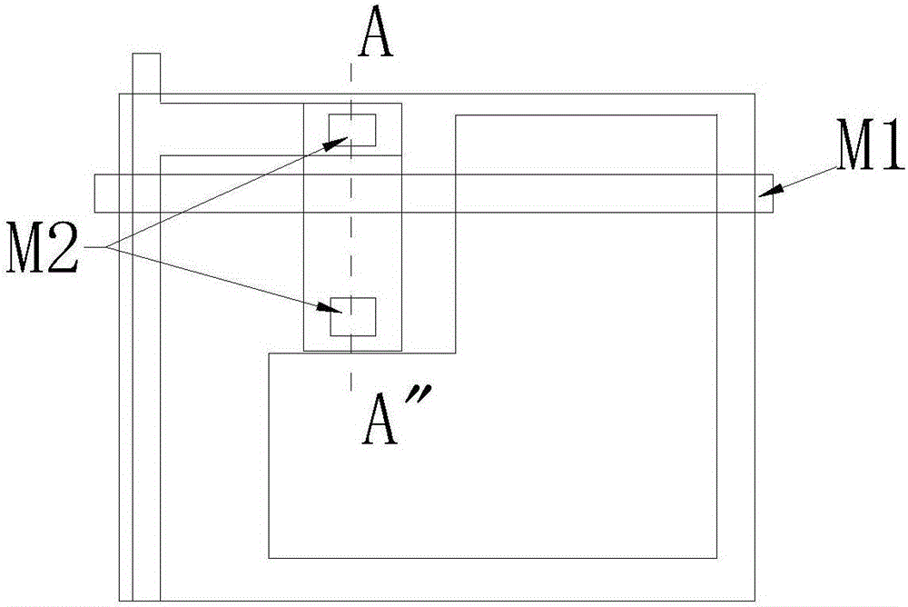
[0026] The fingerprint recognition structure of the present invention is a capacitive sensing structure, please refer to figure 1 , which is a schematic diagram of a capacitive sensing structure fabricated by a method for fabricating a fingerprint identification structure in an embodiment...


PUM


Abstract

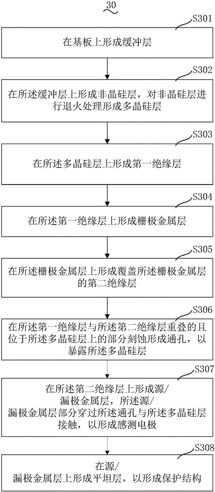
The invention provides a fingerprint identification structure and a manufacturing method thereof. The fingerprint identification structure comprises a polycrystalline silicon layer, a first insulating layer located on the polycrystalline silicon layer, a grid metal layer located on the first insulating layer, a second insulating layer located on the first insulating layer and a source / drain metal layer located on the second insulating layer, wherein the grid metal layer is covered with the second insulating layer. A through hole is formed in the portion, located on the polycrystalline silicon layer, of the overlapped part of the first insulating layer and the second insulating layer, and the source / drain metal layer penetrates through the through hole and is in contact with the polycrystalline silicon layer. The manufacturing method of the fingerprint identification structure is used for manufacturing the fingerprint identification structure. The fingerprint identification structure and the manufacturing method thereof are based on the low-temperature polycrystalline silicon technology, only two-layer metal is adopted, a low-temperature polycrystalline silicon production line can be completely combined, high-accuracy fingerprint identification is achieved, the technological structure is optimized, the production cost is remarkably reduced, and the fingerprint identification structure and the manufacturing method thereof have the good compatibility with an existing LTPS manufacture procedure and are easy to achieve.

Description

technical field [0001] The invention relates to the technical field of information identification, in particular to a fingerprint identification structure and a manufacturing method thereof. Background technique [0002] Fingerprint identification technology is currently the most mature and cheap biometric identification technology. With the continuous iterative development of consumer electronics products, more and more fingerprint identification technologies are used in these electronic products. There are three commonly used fingerprint collection devices on the market. Types: optical type, silicon chip type, and ultrasonic type, which are made of at least three layers of metal, with complex structures and low precision. [0003] At present, the fingerprint identification structure in the industry is usually based on the α-Si process, using optical or capacitive fingerprint identification sensors, made of three or more layers of metal, and the structure is relatively comp...

Claims


Application Information

Patent Timeline
IPC IPC(8): G06K9/00H01L21/768H01L21/28
CPCH01L21/28158H01L21/76838G06V40/13
Inventor 杨冰清郑武田超王勇吴锦坤陈天佑胡君文苏君海李建华
Owner TRULY HUIZHOU SMART DISPLAY
Learn More