
Method and device for computing gain of power units during normal operation of excitation systems

A power unit, normal operation technology, applied in the field of power unit gain calculation, can solve problems such as excitation voltage reference value deviation, power unit gain calculation result deviation, etc.

Inactive Publication Date: 2017-05-17
ELECTRIC POWER RESEARCH INSTITUTE, CHINA SOUTHERN POWER GRID CO LTD +1
View PDF4 Cites 5 Cited by
  • Summary
  • Abstract
  • Description
  • Claims
  • Application Information

AI Technical Summary

Problems solved by technology

[0007] At present, the excitation voltage, excitation current, and commutation reactance are generally used in actual measurement calculations to calculate the no-load output voltage of the rectifier, thereby obtaining the open-loop comprehensive amplification factor, and then obtaining the power unit gain. This method ignores the influence of the commutation voltage drop of the rectifier;
[0008] 2) Dividing the rated excitation voltage by the rated excitation current is used as the reference value of the excitation resistance. It is considered that the excitation winding resistance corresponding to most of the working conditions that need to be simulated is similar to the excitation winding resistance under the rated operating state of the generator, but the excitation winding resistance under the measured state It is likely that there are many deviations from the rated conditions, which will lead to a large deviation of the excitation voltage reference value, resulting in deviations in the calculation results of the power unit gain

Method used


Image

  • Method and device for computing gain of power units during normal operation of excitation systems
  • Method and device for computing gain of power units during normal operation of excitation systems
  • Method and device for computing gain of power units during normal operation of excitation systems

Examples


Embodiment

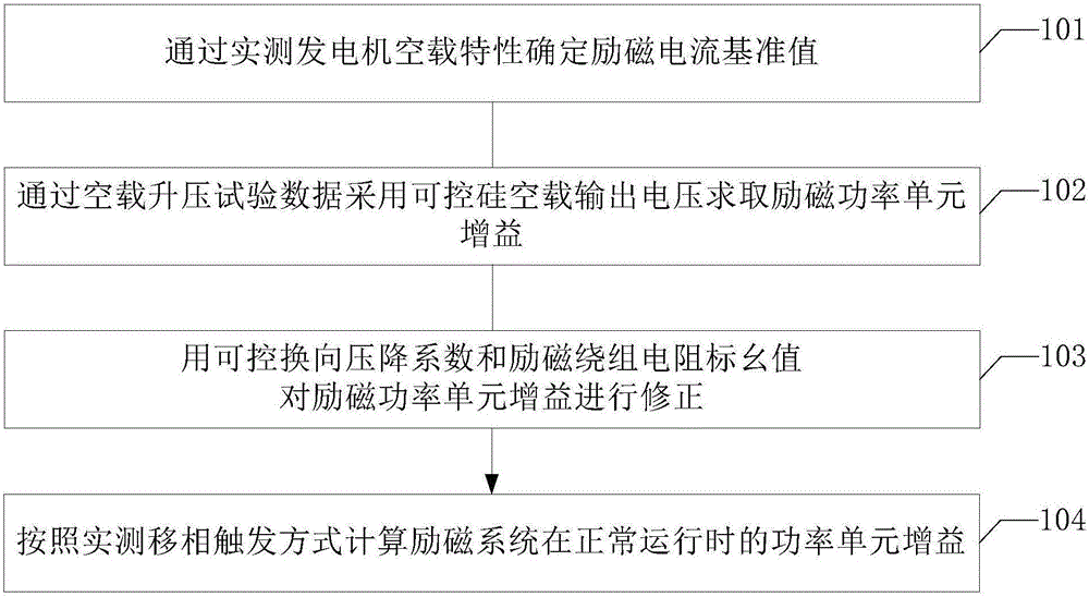
[0032] An embodiment of the present invention provides a method for calculating the power unit gain when the excitation system is in normal operation, combining figure 1 shown, including the following steps:

[0033] 101. Determine the reference value of the excitation current by measuring the no-load characteristics of the generator.

[0034] Specifically, the generator is running at no load, the terminal voltage of the generator is gradually boosted from 0.1p.u. and then stepped down to 0.1p.u., and the maximum boost value should not be lower than 1.2p.u.

[0035] Record the machine terminal voltage, excitation current and excitation voltage at each point during the step-up and step-down process. Average the terminal voltage of the three phases to obtain the average machine terminal voltage, draw two curves of the average machine terminal voltage-excitation current rise and fall, and then average the machine terminal voltage values ​​for the two curves to obtain the no-load...

example 2

[0194] Taking the actual measurement of the open-loop comprehensive gain of the static self-shunt excitation system of Changjiang Nuclear Power Unit 2# as an example, the products of Shanghai ABB Engineering Co., Ltd. Complete phase-shift trigger mode, its test system structure and scheme are as follows Figure 7 shown.

[0195] Such as Figure 8 As shown, first determine the effective air gap line according to the no-load characteristic curve, and then take the excitation current corresponding to the stator rated voltage as the reference value of the excitation current I FDB=1204.8A.

[0196] Select the ratio of the rated excitation voltage on the generator nameplate to the rated excitation current as the reference value of the excitation winding resistance, that is, R FDB =0.1026Ω, then the excitation voltage reference is U FDB =123.57V. The relevant data of the calculated gain are shown in Table 4.

[0197] Table 4 The actual measurement data of the comprehensive gain...


PUM


Abstract

An embodiment of the invention provides a method and a device for computing gain of power units during normal operation of excitation systems, and relates to the field of technologies for modeling power generation and electric power systems. The particular scheme includes that the method comprises measuring no-load characteristics of power generators to determine excitation current reference values; solving the gain of the excitation power units by the aid of output voltages of silicon controlled rectifiers via data of no-load voltage step-up tests; correcting the gain of the excitation power units by the aid of controllable commutation voltage dropping coefficients and resistance per-unit values of excitation windings; computing the gain of the power units during normal operation of the excitation systems according to measured phase-shifted trigger modes. The method and the device have the advantages that the accuracy of computation results of the gain of the power units of the static self-shunt excitation systems of the power generators can be improved; the method and the device can be used for computing the gain of the power units.

Description

technical field [0001] Embodiments of the present invention relate to the technical field of power generation and power system modeling, and in particular to a method and device for calculating the gain of a power unit when the excitation system is in normal operation. Background technique [0002] During the large-scale interconnection of my country's power grid and the combined operation of AC and DC, the problems of large-disturbance power angle stability and small-disturbance stability of regional weakly damped power oscillations are prominent, prompting power grid companies to establish more accurate and effective generator excitation and speed regulation system models. Accurate model parameters are determined through actual measurement to provide accurate basic data for the dynamic analysis of the power grid. [0003] Since 1980, IEEE has released several typical excitation system standard models for power system stability analysis, including DC exciter excitation syste...

Claims


Application Information

Patent Timeline
Patent Type & Authority Applications(China)
IPC IPC(8): G01R31/34
CPCG01R31/34
Inventor 陈刚
Owner ELECTRIC POWER RESEARCH INSTITUTE, CHINA SOUTHERN POWER GRID CO LTD
Learn More