
Pneumatic buffer

A shock absorber and pneumatic technology, applied in the direction of gas shock absorber, shock absorber, shock absorber, etc., can solve the problems of limited spring life and complex structure, and achieve the effect of simple structure

Inactive Publication Date: 2017-05-17
YANGZHOU DAYANG WATER SUPPLY EQUIP
View PDF6 Cites 0 Cited by
  • Summary
  • Abstract
  • Description
  • Claims
  • Application Information

AI Technical Summary

Problems solved by technology

The disadvantages of the spring buffer are: due to the existence of self-vibration, it is easy to transmit low-frequency vibration; the life of the spring is limited; the structure is complex

Method used


Image

  • Pneumatic buffer
  • Pneumatic buffer
  • Pneumatic buffer

Examples


Embodiment Construction

[0019] The present invention will be further described below with reference to the accompanying drawings and specific embodiments, but the protection scope of the present invention is not limited thereto.

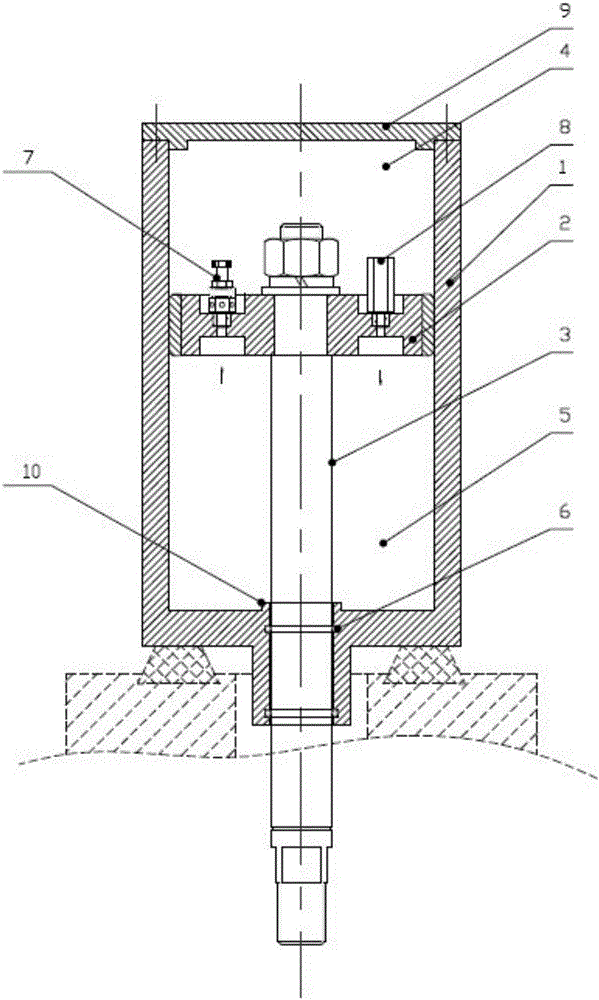
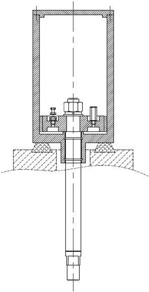
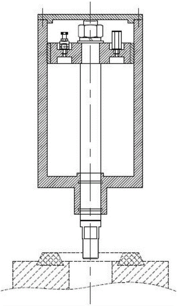
[0020] combine figure 1 As shown, a pneumatic buffer includes a cylinder body 1, an upper cover 9, a piston rod 3 and a piston 2; one end of the cylinder body 1 is provided with an upper cover 9, and the other end is provided with a through hole; the cylinder body 1 and the upper The cover 9 forms a sealing cavity, and the sealing cavity is divided into an upper sealing cavity 4 and a lower sealing cavity 5 by the piston 2; the piston 2 is connected with the piston rod 3 by bolts, and the piston rod 3 passes through the cylinder body 1 The outer edge of the piston 2 is provided with a sealing ring, and the sealing ring is closely fitted with the inner wall of the cylinder body 1; 4. The gas enters the lower sealing chamber 5; the piston 2 is provided with an exhaust hole. ...


PUM


Abstract

The invention provides a pneumatic buffer. The pneumatic buffer comprises a cylinder, an upper cover, a piston rod and a piston. The upper cover is mounted at one end of the cylinder, and a through hole is formed in the other end of the cylinder; a sealed cavity is formed by the cylinder and the upper cover; the sealed cavity is internally divided into an upper sealed cavity body and a lower sealed cavity body through the piston; the piston is connected with the piston rod through a bolt; the piston rod penetrates through the through hole of the cylinder; a seal ring is arranged at the outer edge of the piston and closely attached to the inner wall of the cylinder; a one-way valve is mounted on the piston; air immediately enters the lower sealed cavity body from the upper sealed cavity body as long as the pressure of the upper sealed cavity body is higher than that of the lower sealed cavity body; and an exhausting hole is formed in the piston. By means of the pneumatic buffer, the buffering function can be achieved just by combination of the exhausting hole and the one-way valve, the opening degree of a throttling valve can be adjusted, the absorbing kinetic energy of the buffer is determined, and air in the cylinder is isolated from air outside the cylinder and circulates only inside.

Description

technical field [0001] The invention relates to the field of buffers, in particular to a pneumatic buffer. Background technique [0002] The shock absorber is mainly used to restrain the shock and impact during the rebound. It mainly acts as a buffer, and has less impact to protect other structures in the equipment. Most of the shock absorbers in the prior art are spring-type shock absorbers, which mainly use In the process of compression, the spring can absorb the original shock to play a buffering role. The main purpose of the spring buffer: fans and wind cabinets. Air conditioner box. The shock absorption and vibration isolation of air compressors, air conditioning units, generators, cooling water towers and other equipment can be applied to the vibration isolation of impact equipment such as punching machines and forging hammers if additional dampers are designed. The shortcomings of the spring buffer are: due to the existence of natural vibration, it is easy to transm...

Claims


Application Information

Patent Timeline
IPC IPC(8): F16F9/02F16F9/34
CPCF16F9/0209F16F9/34
Inventor 吴祥昌孙锋
Owner YANGZHOU DAYANG WATER SUPPLY EQUIP
Learn More