
Floor slab hole plugging device and method

A technology for plugging devices and holes, applied in building maintenance, building components, building insulation materials, etc., can solve problems such as large safety hazards, low construction efficiency, unfavorable turnover, etc., to improve construction safety, ensure construction quality, Simple operation effect

Inactive Publication Date: 2017-05-17
CHINA FIRST METALLURGICAL GROUP
View PDF6 Cites 9 Cited by
  • Summary
  • Abstract
  • Description
  • Claims
  • Application Information

AI Technical Summary

Problems solved by technology

[0005] The problems of the above methods are: ①. Manually use a ladder to remove the supporting plate, which has great potential safety hazards and low construction efficiency; ②. The galvanized steel wire is embedded in the concrete, which affects the quality of the concrete and wastes materials; ③. The wood plywood is easy to deform , Opening holes in the wood plywood will easily lead to grout leakage and affect the appearance quality of the concrete; ④Use a crowbar to violently remove the supporting board, which will easily lead to damage to the supporting board and unfavorable turnover; ⑤It is difficult and easy to remove the cement nails nailed into the original concrete Destroy the concrete surface of the original floor slab ceiling

Method used


Image

  • Floor slab hole plugging device and method

Examples


Embodiment Construction

[0027] The present invention will be described in detail below in conjunction with the accompanying drawings and embodiments.

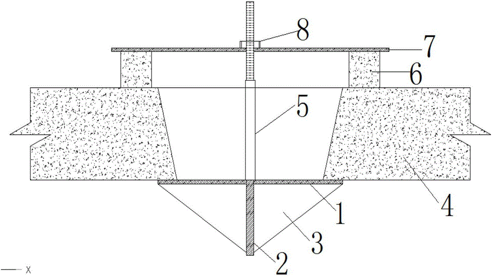
[0028] refer to figure 1 As shown, the floor hole plugging device in an embodiment provided by the present invention includes a supporting plate 1, a tie rod 2 and a fixing plate 7, the supporting plate 1 and the fixing plate 7 are horizontally arranged in parallel, and are distributed on the pulling rod 2 in turn from bottom to top , the tie rod 2 is provided with a sleeve, the length of the sleeve is longer than the thickness of the floor slab, the sleeve is arranged between the supporting plate 1 and the fixing plate 7, the supporting plate 1 is connected and fixed with the pull rod 2 by welding, and the fixing plate 7 Connected with the pull rod 2 through threads, the fixed plate 7 can be adjusted up and down along the pull rod 2 through the threads. The lower end surface of the fixed plate 7 is also provided with a plurality of pads, and the mult...


PUM


Abstract

The invention discloses a floor slab hole plugging device and method. The floor slab hole plugging device comprises a supporting plate, a pulling rod and a fixing plate. The supporting plate and the fixing plate are horizontally and parallelly arranged and distributed on the pulling rod in sequence from bottom to top. The pulling rod is sleeved with a sleeve. The length size of the sleeve is larger than the thickness size of a floor slab. The sleeve is arranged between the supporting plate and the fixing plate. The supporting plate and the pulling rod are connected and fixed through welding. The fixing plate is connected with the pulling rod through a thread and can be moved and adjusted up and down along the pulling rod through the thread. A plurality of cushion blocks are further arranged on the lower end surface of the fixing plate and are uniformly distributed along the center of the fixing plate. During working, the supporting plate covers the lower portion of a floor slab hole, is closely attached to the lower end surface of the floor slab and is used for plugging a lower end opening of the floor slab hole; the pulling rod penetrates through the floor slab hole and is connected with the fixing plate covering the upper portion of the floor slab hole; and the cushion blocks are distributed between the fixing plate and the floor slab. Operation is easy; the construction efficiency and the construction safety are improved; turnover repeated use can be achieved; the construction quality is improved; and the cost is reduced.

Description

technical field [0001] The invention relates to the technical field of building construction, in particular to a floor hole sealing device and method. Background technique [0002] During the construction of the concrete floor slab, some circular or square holes of different sizes are reserved to meet the construction needs such as measurement and hanging objects or the requirements of the design drawings. After the construction of the project is completed, these holes need to be backfilled with concrete. At present, there are generally the following methods for floor hole sealing: [0003] Method 1. The supporting board is made of wood plywood, and the galvanized iron wire is drilled on the supporting board. The lower end of the galvanized iron wire is bound to the clamp (the clamp usually adopts a steel bar head) to fix the pallet, and the upper end of the galvanized iron wire is connected to the fixing rod (the fixing rod is usually The steel bars placed on the concrete...

Claims


Application Information

Patent Timeline
Patent Type & Authority Applications(China)
IPC IPC(8): E04B1/66E04G23/02
CPCE04B1/66E04G23/0203
Inventor 白冲郑涛段强国李少祥郭继舟
Owner CHINA FIRST METALLURGICAL GROUP
Learn More