
A device for laser cladding treatment of plates

A laser cladding treatment and plate technology, applied in metal material coating process, coating and other directions, can solve problems such as can not fundamentally solve the problem, manual operation is random, difficult to operate with high precision, etc. The effect of strong flexibility, simple and lightweight structure, and reduced labor requirements

Active Publication Date: 2018-10-23
芜湖威发电子科技有限公司
View PDF4 Cites 0 Cited by
  • Summary
  • Abstract
  • Description
  • Claims
  • Application Information

AI Technical Summary

Problems solved by technology

[0002] In the practical application of chemical industry, welding, gluing and other industries, especially in small and medium-sized enterprises, when it comes to the application of automation equipment, it is often necessary to complete some important operations manually due to the high price of equipment, especially some In applications that require relatively high precision, they have to hire people with strong operational capabilities to complete the operation, but this cannot fundamentally solve the problem, and the manual operation is random, making it difficult to complete high-precision operations. Only need to manually place the workpiece to be processed on the plate to be processed, and fix the workpiece through the fixture or electromagnet when the power is turned on, and then automatically complete the image acquisition and processing of the workpiece through the vision system, and then send the processed information to the control system , the control system issues a command to realize the action

Method used


Image

  • A device for laser cladding treatment of plates
  • A device for laser cladding treatment of plates
  • A device for laser cladding treatment of plates

Examples


Embodiment Construction

[0023] The present invention will be further described below in conjunction with the accompanying drawings.

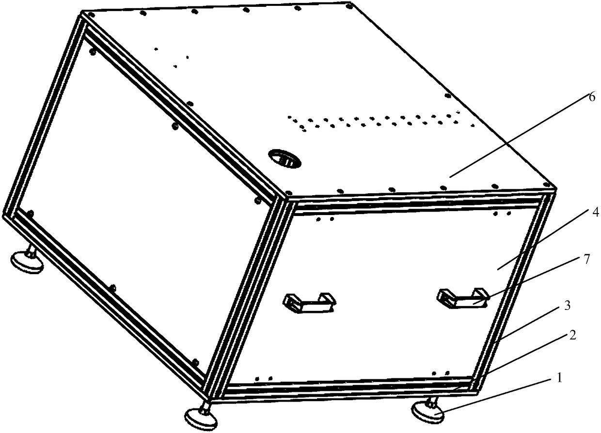
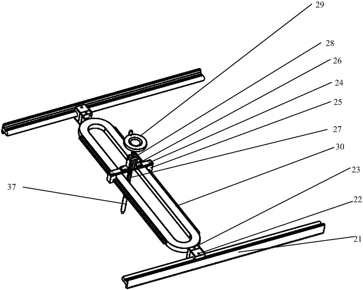
[0024] A device for laser cladding treatment of panels provided by the present invention includes a lower cabinet body 32, a cross electric cylinder, a rotating mechanism 34, a laser cladding mechanism 35, a vision system 36 and an upper support frame.

[0025] The cross electric cylinder comprises a horizontal electric cylinder 8, a vertical electric cylinder 33 and a slide block 12; the cross electric cylinder is fixed on the flat plate 6 of the lower cabinet 32 ​​by screws, and the slide block 12 is fixed on the Above the cross electric cylinder; the rotating mechanism 34 includes a base plate 13, a support column 14, a third driving device 15, an expansion sleeve 16, a workpiece placement tray 19 and a workpiece placement box 17; the base plate 13 is fixed on the On the slider 12, the support column 14 is screwed on the base plate 13, and the workpiece placement bo...


PUM


Abstract

The invention discloses a device for conducting laser cladding treatment on plates and belongs to the technical field of industrial robots. The device comprises a lower cabinet, a cross-shaped electric cylinder, a rotating mechanism, a laser cladding mechanism, a visual system and an upper supporting frame. The cross-shaped electric cylinder comprises a horizontal electric cylinder body, a vertical electric cylinder body and a slide block. The rotating mechanism comprises a bottom plate, supporting posts, a third drive device, an expansion tightening sleeve, a workpiece holding disc and a workpiece holding box. The laser cladding mechanism comprises a horizontal-moving guide rail rack, a small sliding bearing, an upper flat panel, a hand wheel, a lead screw, an L-shaped support, a lower flat panel, a laser head, cushion plates, big sliding bearings and cylindrical linear guide rails. The visual system completes acquisition and processing of workpiece information. Laser cladding treatment for the plates is achieved through coordination of the cross-shaped electric cylinder, the rotating mechanism, the laser cladding mechanism and the drive device. The device is simple in structure, low in weight, high in efficiency and precision and automation degree, low in cost, and capable of being widely applied to various industrial sites.

Description

Technical field: [0001] The invention belongs to the technical field of industrial robots, and in particular relates to a device for laser cladding treatment of plates. Background technique: [0002] In the practical application of chemical industry, welding, gluing and other industries, especially in small and medium-sized enterprises, when it comes to the application of automation equipment, it is often necessary to complete some important operations manually due to the high price of equipment, especially some In applications that require relatively high precision, they have to hire people with strong operational capabilities to complete the operation, but this cannot fundamentally solve the problem, and the manual operation is random, making it difficult to complete high-precision operations. Only need to manually place the workpiece to be processed on the plate to be processed, and fix the workpiece through the fixture or electromagnet when the power is turned on, and th...

Claims


Application Information

Patent Timeline
Patent Type & Authority Patents(China)
IPC IPC(8): C23C24/10
CPCC23C24/10
Inventor 张良安童震权炜炜赵学峰卢杰
Owner 芜湖威发电子科技有限公司
Learn More