Method for determining position of mechanical center of rotating shaft of metal tube cutting system

A metal pipe, center position technology, applied in metal processing machinery parts, metal processing equipment, measuring/indicating equipment, etc., can solve problems such as long measurement time, inaccurate measurement, and complicated measurement steps

Active Publication Date: 2017-05-10
上海柏楚电子科技股份有限公司
View PDF6 Cites 7 Cited by
  • Summary
  • Abstract
  • Description
  • Claims
  • Application Information

AI Technical Summary

Problems solved by technology

Using simple manual measurement and manual input is easy to introduce human measurement error, resulting in inaccurate measurement and long measurement time
Using the measurement method of the tool setting instrument, additional measurement sensors need to be added, the cost is high, and the measurement steps are relatively complicated

Method used


Image

  • Method for determining position of mechanical center of rotating shaft of metal tube cutting system
  • Method for determining position of mechanical center of rotating shaft of metal tube cutting system
  • Method for determining position of mechanical center of rotating shaft of metal tube cutting system

Examples


Embodiment Construction

[0032] The present invention will be further described below according to the accompanying drawings.

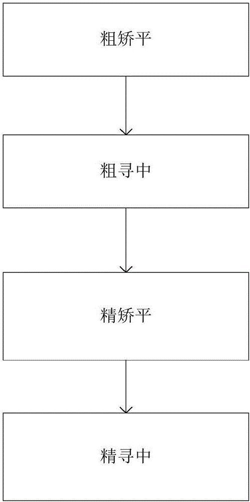
[0033] Such as figure 1 As shown, the method of measuring the mechanical center of the rotating shaft is divided into four steps: rough leveling, rough seeking, fine leveling, and fine seeking.

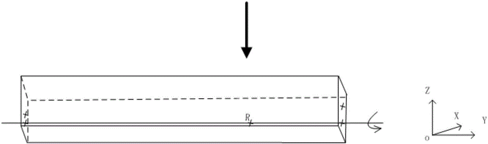
[0034] First, measure the width W and height H of the rectangular metal pipe with a caliper. Then observe to determine whether the sensing head (that is, the cutting nozzle) of the capacitive height controller is above the rectangular metal pipe. If it is not above the rectangular metal pipe, you can click the CNC software to adjust the position of the cutting nozzle. Rough leveling is possible if the cutting nozzle is above the rectangular metal pipe.

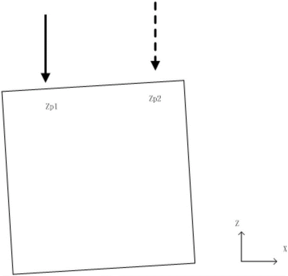
[0035] Coarse leveling operation: the system controls the cutting head to move △X in the positive direction of the X-axis (for safety reasons, △X takes a smaller value), and then measures the Z-axis coordinates of the upper surface...


PUM


Abstract

The invention relates to the field of laser cutting motion control of metal tubes, in particular to a method for determining the position of a mechanical center of a rotating shaft of a metal tube cutting system. In the method for determining the position of the mechanical center of the rotating shaft of the metal tube cutting system, a capacitive height adjustment device is used. The method is characterized by comprising the following specific steps: measuring the width W and the height H of a metal tube by using a caliper; then observing whether a sensing head of the capacitive height adjustment device is above the metal tube or not; if the sensing head of the capacitive height adjustment device is not above the metal tube, adjusting the position of a cutting nozzle; carrying out rough flattening operation; carrying out rough centering operation; carrying out accurate flattening operation; and carrying out accurate centering operation. By the rough flattening operation, the circumstance that the height adjustment device collides with the tube accidently due to excessive inclination of the tube is avoided; by the rough centering operation, the approximate position of the center of the tube is calculated, and the height adjustment device is prevented from pricking the outside of the square tube; after rough flattening and rough centering are carried out, flattening precision is improved by the accurate flattening operation, and flattening is finished; and finally, by the accurate centering operation, high-precision measurement on the mechanical center is finished.

Description

technical field [0001] The invention relates to the field of laser cutting motion control of metal pipes, in particular to a method for measuring the mechanical center position of a rotating shaft of a metal pipe cutting system. Background technique [0002] The center coordinate of the rotation axis of the metal pipe cutting system is an important parameter that needs to be set during the calculation of the tool path of the 3D CNC system. The determination of the center of the rotation axis of the metal pipe cutting system is generally achieved by simple manual measurement and manual input or by expensive tool setting instruments. Using simple manual measurement and manual input is easy to introduce human measurement errors, resulting in inaccurate determination and long measurement time. Using the measurement method of the tool setting instrument requires adding an additional measurement sensor, which is costly and the measurement steps are relatively complicated. Conte...

Claims


Application Information

Patent Timeline
Patent Type & Authority Applications(China)
IPC IPC(8): B23Q17/22
CPCB23Q17/2283
Inventor 鞠勇谢淼邵达周志祥
Owner 上海柏楚电子科技股份有限公司
Why Eureka
Try Eureka