
A method for manufacturing integral wall panels with thin-walled super-high ribs

The technology of an integral wall panel and a manufacturing method is applied in the manufacturing field of thin-wall integral panel, which can solve the problems of inability to manufacture thin-wall integral panel components, and achieves simplified size and structure, long die life and small flow resistance. Effect

Active Publication Date: 2018-09-14
HARBIN INST OF TECH
View PDF5 Cites 0 Cited by
  • Summary
  • Abstract
  • Description
  • Claims
  • Application Information

AI Technical Summary

Problems solved by technology

[0005] The present invention aims to solve the problem that the existing welding, casting, forging and mechanical processing methods cannot manufacture thin-walled integral wall panels with thin-walled super-high rib structures, and proposes a method for manufacturing integral wall panels with thin-walled ultra-high ribs. method

Method used


Image

  • A method for manufacturing integral wall panels with thin-walled super-high ribs
  • A method for manufacturing integral wall panels with thin-walled super-high ribs
  • A method for manufacturing integral wall panels with thin-walled super-high ribs

Examples


specific Embodiment approach 1

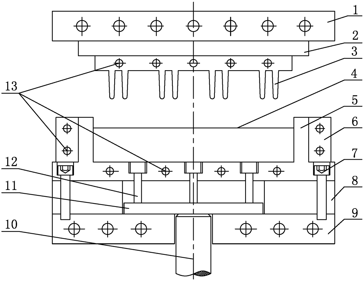
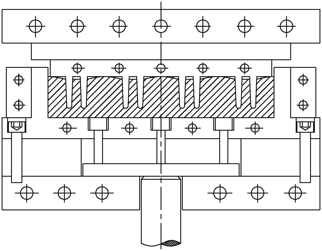
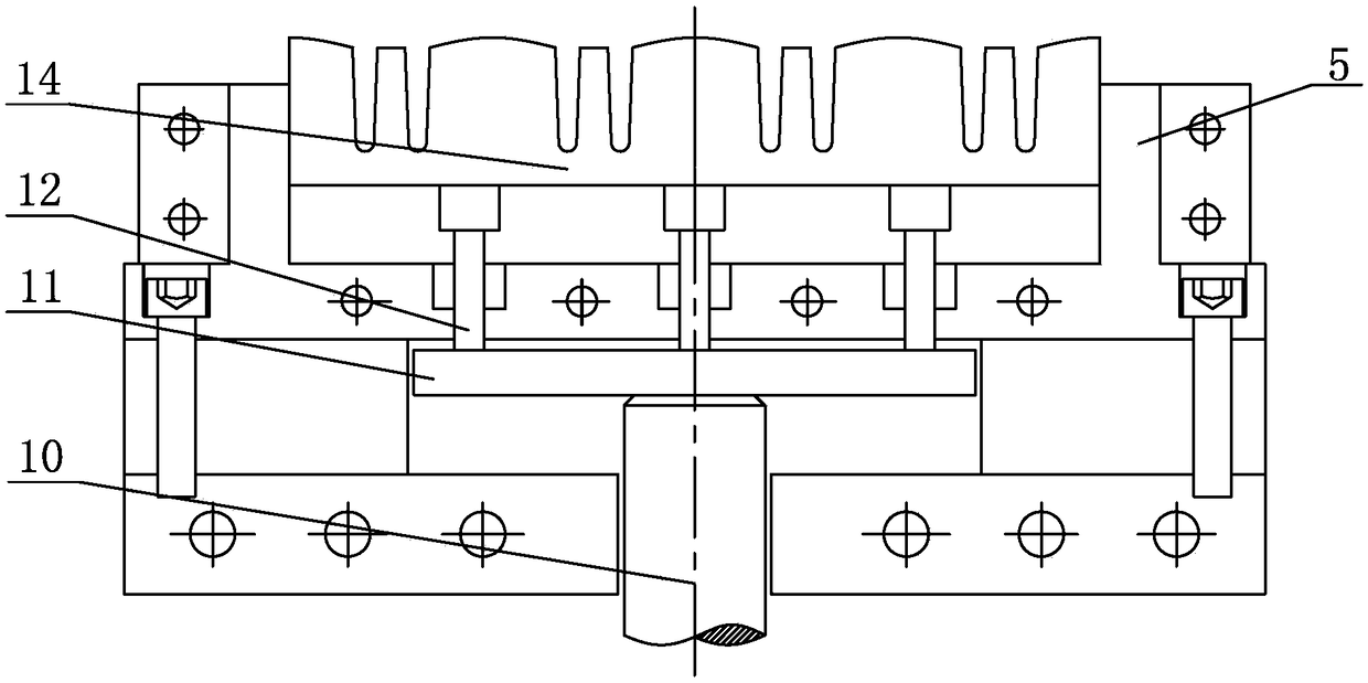
[0032] Specific implementation mode one: combine Figure 1-7 Illustrate, a kind of manufacturing method of the integral panel with thin-walled ultra-high reinforcing rib of this embodiment is realized according to the following steps:

[0033] Step 1, select the original plate with a certain thickness, and make the required smooth slab 4 by cutting and punching;

[0034] Step 2, preheating the blank, putting the slab 4 to be formed into a heating furnace and heating it to (0.5-0.7) Tm, and keeping it warm for a period of time to make the internal temperature of the blank uniform, and Tm is the melting point of the material;

[0035] Step 3, preheating and lubricating the mould, using the electromagnetic induction heating coil 13 and the intermediate heating plate 6 to heat the upper mold 3 and the lower mold 5, and when the upper mold 3 and the lower mold 5 reach the preset temperature, the upper mold 3 and the lower mold 5 are heated. Lubricant is sprayed on the cavity of th...

specific Embodiment approach 2

[0042] Specific implementation mode two: combination figure 1 Note that when the overall size of the thin-walled ultra-high ribs to be processed is small and the processing temperature is low (less than 700°C), the second step can be to place the slab 4 directly into the lower mold 5 and use electromagnetic induction heating The coil 13 and the middle heating plate 6 heat the upper mold 3 and the lower mold 5, and heat the slab 4 to a predetermined temperature through the heat conduction of the upper mold 3 and the lower mold 5. Others are the same as the first embodiment.

specific Embodiment approach 3

[0043] Specific implementation mode three: combination figure 1 , Figure 4 , Figure 6 and Figure 9 Explain that step 1 can cut off a small part of the upper mold cavity filling area ⑤ in the slab 4 through initial simple machining, and the machined grooved slab 20 after processing can be used as the initial slab for hot molding for hot state Molded. Others are the same as the first embodiment.


PUM


Abstract

The invention provides a manufacturing method for an integrated panel with a thin-wall ultrahigh reinforcing rib. The invention relates to the manufacturing method for a thin-wall integrated panel, in order to solve the problem that an integrated panel component with a thin-wall ultrahigh reinforcing rib structure cannot be manufactured using the present welding, casting, forging and machining method. The manufacturing method comprises the following steps: 1) manufacturing a required panel blank using cutting and blanking methods; 2) preheating the panel blank and causing the internal temperature of the panel blank to be uniform; 3) preheating and lubricating a mold; 4) transferring the preheated panel blank onto a lower mold and positioning, and then utilizing an upper mold for pressure forming on the panel blank; 5) opening the upper mold, taking out the pressure formed panel-shaped part and cooling to room temperature; 6) machining, removing the material in a material storage area on the panel-shaped part by using a cutting processing method to obtain the final integrated panel with the thin-wall ultrahigh reinforcing rib. The method provided by the invention is used for manufacturing the integrated panel with the thin-wall ultrahigh reinforcing rib.

Description

technical field [0001] The invention relates to a method for manufacturing a thin-walled integral wallboard, in particular to a method for manufacturing an integral wallboard with thin-walled superhigh ribs. Background technique [0002] In the fields of aviation, spaceflight and weaponry, realizing lightweight structure is one of the most important goals pursued. In order to reduce the weight of the structure, it is necessary to optimize the design of the components under the premise of meeting the requirements of use. For example, on rockets or missiles, there are many thin-walled and high-rib structures, such as the integral wall panels of rocket fuel storage tanks, fairings of missiles, etc. Such thin-walled structures are usually composed of thin-walled webs and stiffeners, and the stiffness and strength of thin-walled webs can be significantly improved by rationally setting stiffeners. Sometimes, it is also necessary to cover the stiffener with a thin-walled skin to ...

Claims


Application Information

Patent Timeline
Patent Type & Authority Patents(China)
IPC IPC(8): B23P15/00
CPCB23P15/00
Inventor 苑世剑何祝斌张学宇凡晓波
Owner HARBIN INST OF TECH
Learn More