Mine radial automatic flow dividing device and control method thereof

A technology of automatic flow separation and control method, which is applied in chemical instruments and methods, grading, solid separation, etc. It can solve problems such as inability to sort minerals, complicated work sections, and difficult equipment processing, so as to achieve fast and complete screening, avoid accumulation, and save Effects of time and energy

Inactive Publication Date: 2017-05-03
郑小蓉
View PDF0 Cites 2 Cited by
  • Summary
  • Abstract
  • Description
  • Claims
  • Application Information

AI Technical Summary

Problems solved by technology

[0002] In the existing mine mining process, belt conveyors are used for the transportation of minerals, which are used to transport a large amount of bulk minerals. They have the characteristics of large transportation volume, easy control, and long-distance transportation, so they are widely used. The conveyor belt has its unavoidable defects. Its operation is to drive the minerals through the friction of the conveyor belt itself, which is easy to wear, inconvenient to replace, and has a short service life. In the case of a large impact, the transportation volume and continuous stability of transportation are greatly limited, especially in the case of mineral accumulation in individual sections, or the inclined section is extremely worn
In addition, for the transportation and subsequent processing of minerals, the conveyor belt can only play the role of transportation, and cannot sort the minerals during the transportation process, so that subsequent processing can be carried out quickly after the transportation is completed. In addition, more processes are set to make the work section more complicated
Minerals that cannot be sorted will also cause processing difficulties and waste of energy to subsequent equipment during the processing process

Method used


Image

  • Mine radial automatic flow dividing device and control method thereof
  • Mine radial automatic flow dividing device and control method thereof

Examples


Embodiment Construction

[0026] Below in conjunction with accompanying drawing, the present invention will be further described:

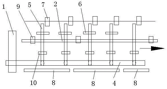
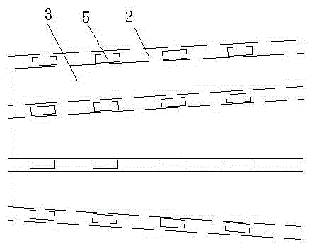
[0027] as attached figure 1 and 2 As shown, a kind of mine radial automatic diversion device of the present invention is connected with a power control device at one end, and the power control device controls the operation of the whole diversion device. One group, two conveying bars in each group are arranged in parallel and spaced apart from each other. This interval is used to push the rack to run, similar to the guide rail, pushing the rack to advance along the guide rail. The interval between each group of conveying bars Open to form a conveying gap, the conveying gap is used to make the minerals smaller than the gap fall to the conveyor belt set below, and the circular transmission device driven by the power control device is arranged under the conveyor belt, and the circular transmission device drives the rack to push the lower end of the rack It is connected to th...


PUM


Abstract

The invention relates to a mine radial automatic flow dividing device and a control method thereof, and relates to the field of mine equipment. The mine radial automatic flow dividing device comprises a power control device and multiple sets of conveying strips. A conveying gap is formed between the conveying strips in each group. The two conveying strips are arranged in each group. A structure similar to a guide rail is formed between every two conveying strips so that a corresponding push rack can advance to push minerals to run along the conveying strips. Each push rack is provided with branch strips, a stop block is arranged above each push rack, and the overturning and vibrating effects are formed for the minerals in the running process. Conveying belts are arranged below the push racks, and after the minerals different in size are sorted through the conveying gaps, the minerals are conveyed to the subsequent workshop section through the conveying belts. By the adoption of the device and the method, the minerals can be rapidly transported, the minerals are subjected to timely sorting treatment in the transporting process, the transporting process is in linkage with the subsequent workshop section, the transporting links are reduced, and the energy of the whole workshop section is saved.

Description

technical field [0001] The invention relates to mine mineral transportation equipment, in particular to a radial automatic diversion device for mines that automatically transports and sorts minerals and a control method for processing minerals through the device. Background technique [0002] In the existing mine mining process, belt conveyors are used for the transportation of minerals, which are used to transport a large amount of bulk minerals. They have the characteristics of large transportation volume, easy control, and long-distance transportation, so they are widely used. The conveyor belt has its unavoidable defects. Its operation is to drive the minerals through the friction of the conveyor belt itself, which is easy to wear, inconvenient to replace, and has a short service life. In the case of a large impact, the transportation volume and continuous stability of transportation are greatly limited, especially in the case of mineral accumulation in individual sectio...

Claims


Application Information

Patent Timeline
Patent Type & Authority Applications(China)
IPC IPC(8): B65G15/12B07B13/065
Inventor 郑小蓉
Owner 郑小蓉
Why Eureka
Try Eureka