
Mutual-coupling-contained time modulation array synthesis method based on difference evolution algorithm

A differential evolution algorithm and time modulation technology, applied in antenna arrays, calculations, calculation models, etc., can solve the problems of slow beamforming speed, long calculation time, and fast calculation without considering time modulation arrays.

Inactive Publication Date: 2017-04-26
XIAMEN UNIV
View PDF2 Cites 8 Cited by
  • Summary
  • Abstract
  • Description
  • Claims
  • Application Information

AI Technical Summary

Problems solved by technology

[0003] Chinese patent 201410605142.0 discloses a beamforming method based on a time modulation array, which mainly solves the problem that the existing time modulation array has many optimization variables, the beamforming speed is slow, the optimization ability is poor, and it is easy to fall into a local optimal solution.
[0004] Chinese patent 201410675266.6 discloses a fast pattern synthesis method based on time-modulated conformal phased array, which mainly solves the problem that the existing time-modulated conformal phased array pattern synthesis speed is slow, the calculation amount is large, the stability is not high, and it cannot be used in real-time Computing Platform Issues
[0005] The above studies have not considered the fast calculation of the actual time-modulated array with mutual coupling effects. When using, for example, the differential evolution algorithm to optimize the radiation pattern of the time-modulated array, a large number of repeated calculations of the center frequency and sideband direction are required during the evolution process. Figure, the calculation time is long, because the mutual coupling effect of the time modulation array is considered, the active pattern of each array element is not the same, the array factor cannot be extracted, and the fast Fourier transform (FFT) cannot be used to quickly calculate the array pattern

Method used


Image

  • Mutual-coupling-contained time modulation array synthesis method based on difference evolution algorithm
  • Mutual-coupling-contained time modulation array synthesis method based on difference evolution algorithm
  • Mutual-coupling-contained time modulation array synthesis method based on difference evolution algorithm

Examples


specific Embodiment

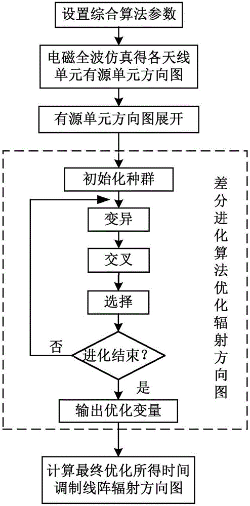
[0023] refer to figure 1 , the present invention provides a kind of specific embodiment, and its implementation steps are as follows:

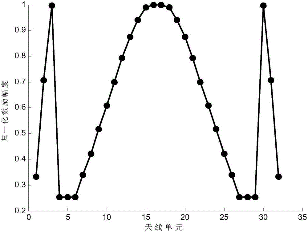
[0024] Step 1: According to the system application index, determine the number of elements of the time-modulated linear array N=32, the unit antennas are all dipole antennas, and the center frequency is f 0 = 3GHz, time modulation frequency f prf =1MHz, array element spacing d=0.5λ, λ is the wavelength at the center frequency; set target parameters: center frequency f 0 The expected maximum sidelobe level SLL of the radiation field pattern at d =-50dB, the first sideband f 0 +f prf The maximum expected level SBL of the radiation field pattern at d =-32.2dB, static excitation amplitude value A n The search range is [0.252,1], the pulse duration τ n The search range of is [0.06,1];

[0025] Step 2: Obtain the active unit pattern g of each unit antenna in the N-unit time-modulated linear array through full-wave electromagnetic simulation ...


PUM


Abstract

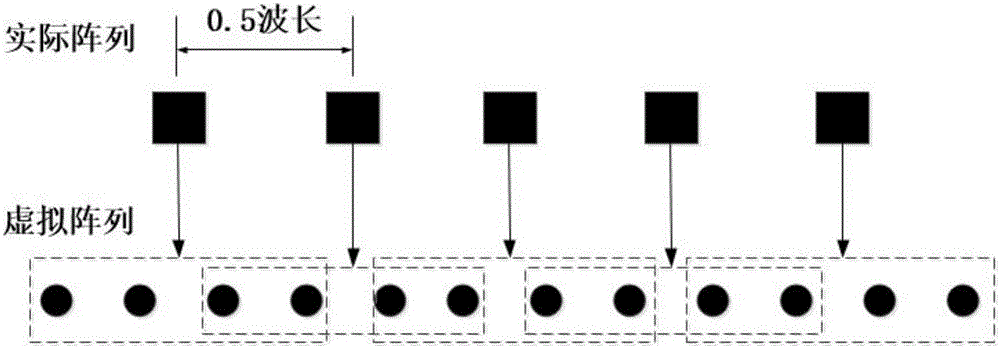
The invention relates to a mutual-coupling-contained time modulation array synthesis method based on a difference evolution algorithm and relates to an antenna. An array element quantity, a unit form, an array element interval, center frequency and time modulation frequency of a time modulation linear array are determined according to a system application index, and target parameters are set; full wave electromagnetic simulation is carried out to acquire an active unit pattern of each unit antenna of the N-unit time modulation linear array; after expansion of each active unit pattern, a mutual-coupling-contained time modulation array pattern expression capable of realizing rapid calculation through utilizing FFT is acquired; static excitation amplitude and pulse duration time can be taken as optimization variables, a largest sidelobe level of a radiation field pattern at a center frequency f0 portion and a largest level of the radiation field pattern at a first sideband f0+fprf portion are taken as optimization targets, and a time modulation linear array radiation pattern is optimized to acquire a static excitation amplitude An and the pulse duration time taun of each antenna unit; a time modulation linear array radiation pattern through final optimization is calculated according to the An and the taun.

Description

technical field [0001] The invention relates to antennas, in particular to a method for synthesizing an array with mutual coupling time modulation based on a differential evolution algorithm. Background technique [0002] Compared with traditional antenna arrays, time-modulated arrays can achieve lower dynamic ratios of static excitation amplitudes, and have greater advantages in low / ultra-low sidelobe pattern synthesis, and have attracted more attention in recent years. The research on time-modulated arrays mainly includes sidelobe reduction and sideband suppression, zero point scanning, beam pointing control, signal direction of arrival estimation and so on. At present, the differential evolution algorithm, particle swarm algorithm, and genetic algorithm are mostly used in the synthesis of time-modulated arrays. Most of these studies are based on the fact that the array elements are isotropic. In fact, the sidelobe level of the array pattern is greatly affected by the mu...

Claims


Application Information

Patent Timeline
Patent Type & Authority Applications(China)
IPC IPC(8): H01Q21/00G06F17/50G06N3/00
CPCG06N3/006G06F30/20G06F2111/06H01Q21/0087
Inventor 刘颜回廖海艳徐开达叶龙芳黄鑫柳清伙
Owner XIAMEN UNIV
Learn More