Binocular visual multi-line projection structured light calibration method

A binocular vision and calibration method technology, applied in image data processing, instruments, calculations, etc., can solve the problems of high precision of three-dimensional targets, increased complexity of multi-line structure cursor calibration, increased complexity, and measurement time.

Inactive Publication Date: 2017-04-26
SOUTH CHINA UNIV OF TECH
View PDF2 Cites 19 Cited by
  • Summary
  • Abstract
  • Description
  • Claims
  • Application Information

AI Technical Summary

Problems solved by technology

[0005] In practical applications, in order to improve the measurement efficiency, a multi-line structured light measurement system is designed. The multi-line structured light brings the problem of increased calibration complexity and matching.
Calibration of structured light needs to know the information of the characteristic points or characteristic lines of the structured light surface. The commonly used methods are to use plane targets and three-dimensional targets: the method of using three-dimensional targets needs to know the parameters of the three-dimensional target, and the accuracy of the three-dimensional target directly affects the calibration results. This type of method The high precision of the three-dimensional target increases the difficulty and cost of three-dimensional target processing, or assists in obtaining three-dimensional parameters with three-dimensional measuring equipment, which increases the complexity and measurement time; the method of using a plane target to calibrate the binocular structured light, such as Sun Changku et al. The proposed binocular structure cursor calibration method needs the assistance of precise moving guide rails, which has the disadvantages of high equipment cost and cumbersome process.

Method used


Image

  • Binocular visual multi-line projection structured light calibration method
  • Binocular visual multi-line projection structured light calibration method
  • Binocular visual multi-line projection structured light calibration method

Examples


Embodiment

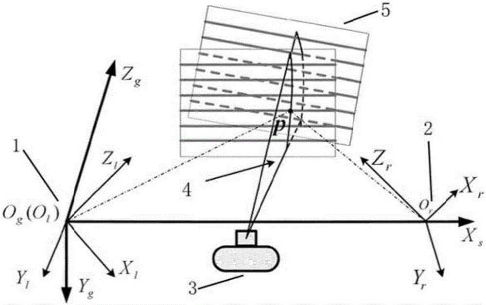
[0048] like figure 1 As shown, it is a schematic diagram of binocular vision multi-line projection structured cursor calibration. In the figure, only one structured light and two calibration board positions are drawn, as shown in figure 1 As shown, the binocular vision multi-line projection structured light system includes: a left camera 1, a right camera 2, a projector 3, a structured light plane 4, and a calibration plate 5, wherein, O l (X l ,Y l ,Z l ) is the left camera coordinate system, O r (X r ,Y r ,Z r ) is the right camera coordinate system, O g (X s ,Y g ,Z g ) is the system camera coordinate system, and point p is an intersection point between the structured smooth surface and the white line in the calibration plate; the left camera 1 and the right camera 2 are fixed on a platform to form a binocular vision system; the projector 3 is fixed In the middle of the left camera 1 and the right camera 2, so that the projected multi-line structured light is wit...


PUM


Abstract

The invention discloses a binocular visual multi-line projection structured light calibration method. The method comprises the following steps that 1) the sequence numbers of light stripes are determined; 2) left and right cameras collect a lattice image, four corners of a lattice are clicked, initial estimated positions of other intersection points in the lattice are obtained, and sub-pixel coordinates of intersection points are obtained by using an Ostu threshold method and a gray scale weighted average method in a k*k neighborhood of the initial estimated positions of intersection points; 3) 3D coordinates of the intersection points are obtained; and 4) the steps 1-3 are repeated, the 3D coordinates of the intersection points obtained in multiple times are classified according to the sequence numbers of the light stripes, for all points belonging to the same structured light plane, a least square method is used to carry out planar fitting on the 3D coordinates of the intersection points belongs to the same structured light to obtain a plane equation, and calibration is not completed until all the structured light planes are in the planar equation of the system coordinate system. The method has the advantages that a calibration board has no requirements for planarization, manufacture is simple, calibration is flexible, no auxiliary equipment is needed, the method is suitable for onsite calibration and the versatility is high.

Description

technical field [0001] The invention belongs to the field of machine vision structured light three-dimensional measurement, and in particular relates to a binocular vision multi-line projection structured light calibration method. Background technique [0002] Structured light 3D measurement is one of the most promising 3D data acquisition methods in engineering applications in recent years. It has the advantages of non-contact, fast speed, high precision, and strong anti-interference. significance and application prospects. [0003] The principle of structured light measurement is based on the triangulation method. The optical projector projects the structured light pattern onto the surface of the measured object, and the camera collects the distorted pattern on the surface of the measured object, and restores the surface profile through the distortion of the pattern. By calibrating structured light, a camera and an optical projector can realize surface profile measurement...

Claims


Application Information

Patent Timeline
Patent Type & Authority Applications(China)
IPC IPC(8): G06T7/80
CPCG06T2207/10004
Inventor 杨荣骞肖伟虎
Owner SOUTH CHINA UNIV OF TECH
Why Eureka
Try Eureka