
CPU (Central Processing Unit) control board capable of realizing hot plug of board card and implementation method thereof

A control board and board technology, which is applied in hardware monitoring, instruments, electrical digital data processing, etc., can solve problems such as misoperation of board remote control exit, deadlock of other processes, hardware damage, etc., to achieve reliable work, improve efficiency, Simple effect of hardware design

Inactive Publication Date: 2017-04-26
INTEGRATED ELECTRONICS SYST LAB
View PDF5 Cites 11 Cited by
  • Summary
  • Abstract
  • Description
  • Claims
  • Application Information

AI Technical Summary

Problems solved by technology

However, due to the switching on or off of the power supply and data interface during the hot plugging process of the current board, a certain degree of power surge will be generated on the data line or signal line, which is very prone to hardware damage or damage, and may also cause other problems. The remote control outlet of the board card (such as remote control, remote adjustment board) malfunctions, causing certain economic losses; if the board card is being accessed by other processes, the board card and the system have data interaction, and the removal of the board card may cause other processes to deadlock Even the whole system crashes

Method used


Image

  • CPU (Central Processing Unit) control board capable of realizing hot plug of board card and implementation method thereof
  • CPU (Central Processing Unit) control board capable of realizing hot plug of board card and implementation method thereof
  • CPU (Central Processing Unit) control board capable of realizing hot plug of board card and implementation method thereof

Examples


Embodiment Construction

[0034] The structure and implementation method of the present invention will be described in detail below in conjunction with the accompanying drawings.

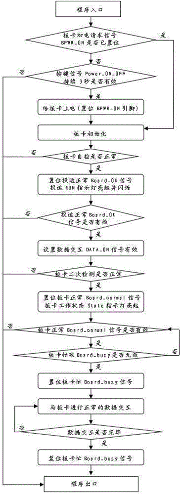
[0035] Such as figure 1 Shown is a schematic structural diagram of a CPU control board capable of hot-swapping boards, including: a CPU, an IO module, a power control module, and a data interface module. Card signal detection, human-computer interaction, input and output instructions, the CPU realizes the power supply to the board card through the power control module, the CPU uses the data interface to manage the data interface module, and the CPU uses the data bus and The data interaction with the board is realized through the data interface module; the control program for realizing the hot swap of the board is stored in the CPU control board.

[0036] In the specific implementation, it is also necessary to set a button in the IO module of the CPU control board to realize the human-computer interaction function. By pressi...


PUM


Abstract

The invention discloses a CPU (Central Processing Unit) control board capable of realizing hot plug of a board card and an implementation method thereof. The CPU control board comprises a CPU, an IO (Input Output) module, a power control module and a data interface module, and is characterized in that the CPU implements signal detection, man-machine interaction and input output indication on the board card via the IO module, supplies power to the board card via the power control module, manages the data interface module by using a data interface, and exchanges data with the board card by using a data bus and the data interface module; and a control program for realizing hot plug of the board card is stored in the CPU control board. The CPU control board and the implementation method thereof avoid the problems of hardware damage, misoperation and the like in the hot plug process of the board card, also avoid the problems of program locking and system crash caused by abnormal unplugging of the board card, and simultaneously improve the efficiency of field work.

Description

technical field [0001] The invention relates to the field of power distribution automation in electric power systems, in particular to a CPU control board capable of hot plugging of boards and a method for realizing the same. Background technique [0002] After the power system distribution automation terminal products are put into on-site operation, board cards are often inserted or replaced due to maintenance needs. It is carried out in the case of power failure, and after the terminal unit is plugged or replaced, it generally needs to complete a series of tasks such as reset, self-test, and initialization every time it is powered on, and it takes a long period of time. It affects the work efficiency of on-site maintenance personnel. [0003] In order to improve the working mechanism of plugging or replacing terminal units in the case of power failure, save on-site personnel maintenance time, and improve work efficiency, the demand for hot-swapping operation of boards and...

Claims


Application Information

Patent Timeline
Patent Type & Authority Applications(China)
IPC IPC(8): G06F13/40G06F11/30
CPCG06F13/4081G06F11/3031
Inventor 崔士军张立伟刘冰李永岗
Owner INTEGRATED ELECTRONICS SYST LAB
Learn More