
VPSA large-capacity centrifugal vacuum pump

A technology of vacuum pumps and high volume, applied in the direction of pumps, pump components, non-variable pumps, etc., can solve problems such as low pumping efficiency, unstable influence, and adsorbent failure

Pending Publication Date: 2017-04-26
JIANGSU ASIA PACIFIC IND PUMP TECH DEV CO LTD
View PDF0 Cites 1 Cited by
  • Summary
  • Abstract
  • Description
  • Claims
  • Application Information

AI Technical Summary

Problems solved by technology

Although the water ring vacuum pump has a large pumping capacity, the vacuum degree varies greatly with the suction flow rate, and the actual pumping efficiency is low. Multiple units need to be used in parallel, which consumes a lot of water, and the vacuum degree is low and unstable due to the influence of water quality. The phenomenon of backflow of water causes the failure of expensive adsorbents, especially the water pollution caused by the contact of water with the medium, which requires manpower and material resources for sewage treatment, which is very inconsistent with the current national concept of energy conservation and environmental protection
Although the piston vacuum pump has the advantages of no oil lubrication and no water pollution, due to structural limitations, the largest piston vacuum pump in China can only reach 17280 m3 / h. The suction flow rate will decrease with the increase of the vacuum degree. The efficiency is low, and often requires multiple parallel connections to meet the requirements, which is far from meeting the needs of the rapid development of the petrochemical industry and the coal chemical industry in recent years

Method used


Image

  • VPSA large-capacity centrifugal vacuum pump
  • VPSA large-capacity centrifugal vacuum pump

Examples


Embodiment Construction

[0011] Below in conjunction with accompanying drawing, the specific embodiment of the present invention is described in further detail:

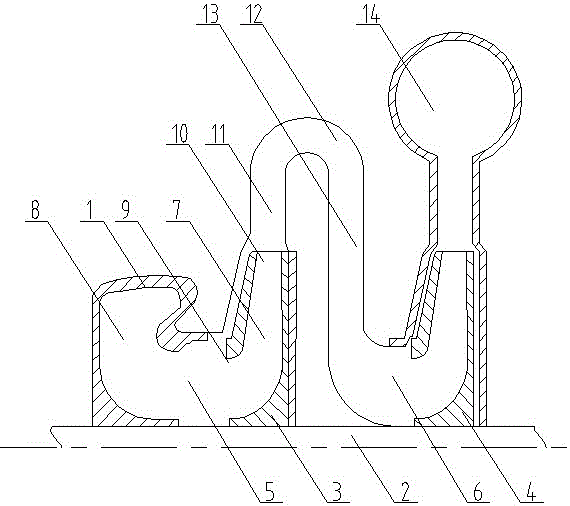
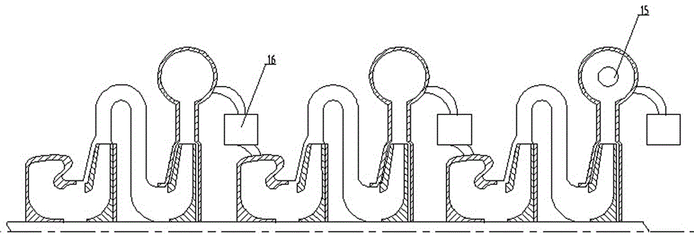
[0012] As shown in the figure, the VPSA large-capacity centrifugal vacuum pump includes three-stage vacuum pump units connected in series. Each vacuum pump unit includes a housing 1, a rotating shaft 2, and impellers 3 and 4. The housing of the three-stage vacuum pump unit is integrally cast. Each housing 1 includes two-stage chambers 5 and 6, and impellers are respectively installed in the chambers of each stage, and the impellers 3 and 4 are provided with L-shaped air passages 7 for axial air intake and radial air outlet, and each impeller is fixed It is connected in series with the rotating shaft 2; the front section of the first-stage chamber 5 is an air intake chamber 8, and the air intake chamber is a double-supported radial air intake mechanism. The air inlet 9 of the impeller 3 communicates with the air inlet chamber, and a pair of f...


PUM


Abstract

The invention relates to a VPSA large-capacity centrifugal vacuum pump. A backward bending type three dimensional impeller and a vaneless diffuser are adopted in each stage of the VPSA large-capacity centrifugal vacuum pump, a cooler is installed between every two sections, a cooler is installed on the outlet of the last section, and three coolers exist. An air inlet chamber and an air outlet spiral chamber are installed in every section, and three air inlet chambers and three air outlet spiral chambers exist. The air inlet chambers are double bracing radial air inlet chambers, and the air outlet spiral chambers are circular symmetrical spiral chambers. When the VPSA large-capacity centrifugal vacuum pump works, air is sucked through the air inlet chambers and rotates at high speed with the first-stage impeller; under the effect of centrifugal force, the kinetic energy and the static energy of the air are increased and threw out through passageways among vanes in the radial direction, and enter the first-stage diffuser with a gradually enlarged passageway area; the kinetic energy of the air is reduced and conversed into the static energy, the pressure of the air is increased, and then the air passes through a first-stage bending way and a return device and enters the second stage to be compressed continuously. Cyclic compression is conducted in sequence, after the last compression is completed, and the air is collected through a spiral shell and discharged through an exhaust pipe. As the exhausting process is conducted continuously, the mass flow rate is continuously reduced, inlet pressure is continuously reduced, the vacuum degree is continuously improved, and until the next cycle period, a unit is under the operating process with continuous changeable working conditions.

Description

technical field [0001] The invention relates to a vacuum pump, in particular to a VPSA large volume centrifugal vacuum pump. Background technique [0002] The existing VPSA large-scale vacuum pumps involved in the petrochemical industry and coal chemical industry are all water ring vacuum pumps or piston vacuum pumps. Although the water ring vacuum pump has a large pumping capacity, the vacuum degree varies greatly with the suction flow rate, and the actual pumping efficiency is low. Multiple units need to be used in parallel, which consumes a lot of water, and the vacuum degree is low and unstable due to the influence of water quality. The phenomenon of backflow of water causes the failure of expensive adsorbents, especially the water pollution caused by the contact of water with the medium, which requires manpower and material resources for sewage treatment, which is very inconsistent with the current national concept of energy conservation and environmental protection. A...

Claims


Application Information

Patent Timeline
Patent Type & Authority Applications(China)
IPC IPC(8): F04D17/12F04D29/00F04D29/28F04D29/44F04D29/58
CPCF04D17/12F04D29/002F04D29/286F04D29/441F04D29/5846
Inventor 薛建国刘琴
Owner JIANGSU ASIA PACIFIC IND PUMP TECH DEV CO LTD
Learn More