
Device for changing tail gas afterheat of automobile engine into electric energy

A technology for automobile engine and automobile exhaust, which is applied to exhaust devices, engine components, combustion engines, etc., to reduce energy waste and solve exhaust pollution.

Inactive Publication Date: 2017-04-26
李竟儒
View PDF5 Cites 1 Cited by
  • Summary
  • Abstract
  • Description
  • Claims
  • Application Information

AI Technical Summary

Problems solved by technology

[0003] The purpose of the present invention is to overcome the deficiencies in the prior art, and provide a device for converting exhaust heat of automobile engine exhaust into electric energy.

Method used


Image

  • Device for changing tail gas afterheat of automobile engine into electric energy

Examples


Embodiment

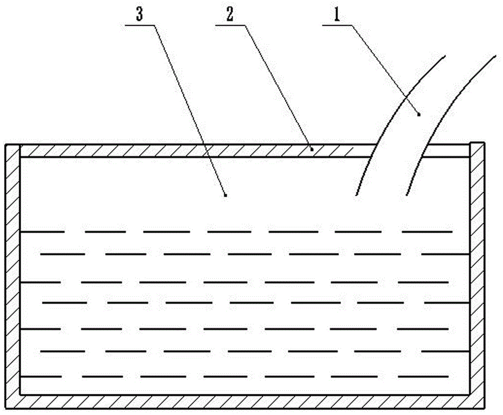
[0015] Such as figure 1 As shown, a device for converting waste heat of automobile engine exhaust into electric energy, the device is arranged on a sewage heat dissipation barrel 3 and a solar panel 2 arranged on the surface of the sewage heat dissipation barrel 3, and the sewage heat dissipation barrel 3 is arranged behind or below the automobile cab .

[0016] The outer surface of the sewage cooling bucket 3 is provided with cooling fins to radiate the solar panel 2 .

[0017] The sewage cooling barrel 3 is not completely non-closed, but is provided with an opening, and the opening is connected with the exhaust pipe 1 of the automobile.

[0018] The sewage cooling barrel 3 is 80-120cm long, 40-50cm wide, and 40-50cm high.

[0019] The depth of the liquid in the sewage cooling bucket 3 is two-thirds of the height of the sewage cooling bucket, and the automobile exhaust pipe 1 is not in contact with the liquid.

[0020] When the car is running, the exhaust pipe 1 of the car...


PUM


Abstract

The invention discloses a device for changing tail gas afterheat of an automobile engine into electric energy. The device comprises a sewage heat-dissipating barrel and a solar battery panel arranged on the surface of the sewage heat-dissipating barrel, wherein the sewage heat-dissipating barrel is arranged behind or below an automobile cab. The device effectively solves the problem of tail gas pollution, effectively collects and recycles the tail gas afterheat and reduces waste of energy.

Description

technical field [0001] The invention relates to the technical field of automobile exhaust treatment, in particular to a device for converting waste heat of automobile engine exhaust into electric energy. Background technique [0002] With the rapid development of social economy, the use of automobiles is becoming more and more common, and the use of automobiles is becoming more and more extensive. Most of them are ordinary fuel internal combustion locomotives. At present, the exhaust gas of automobiles is generally directly discharged into the atmosphere. While meeting the needs of people's travel convenience, more and more people pay more and more attention to the treatment of automobile exhaust and the recovery of waste heat from exhaust. However, in the existing technology, tail gas treatment and tail gas waste heat recovery cannot be processed at the same time. Contents of the invention [0003] The purpose of the present invention is to overcome the deficiencies in t...

Claims


Application Information

Patent Timeline
Patent Type & Authority Applications(China)
IPC IPC(8): F01N3/04F01N5/02
CPCF01N3/04F01N5/025Y02T10/12
Inventor 李竟儒
Owner 李竟儒
Learn More