Design and construction technology of self-stabilized section steel suspended scaffold

A construction technology and scaffolding technology, which is applied in the direction of scaffolding for building structure support, building structure support, building structure support, etc., and can solve the problems of long period, large amount of embedded parts, and high construction cost

Active Publication Date: 2017-04-26
SHANDONG WANXIN CONSTR
View PDF8 Cites 10 Cited by
  • Summary
  • Abstract
  • Description
  • Claims
  • Application Information

AI Technical Summary

Problems solved by technology

In addition, the steel cantilevered scaffold needs to embed a large number of steel wire rope rings and steel beam anchor rings in the floor concrete. The embedded parts are large and cannot be reused. The installation and removal process is cumbersome, and the construction cost is high and the period is long.

Method used


Image

  • Design and construction technology of self-stabilized section steel suspended scaffold
  • Design and construction technology of self-stabilized section steel suspended scaffold
  • Design and construction technology of self-stabilized section steel suspended scaffold

Examples


Embodiment Construction

[0125] The present invention will be further described below in conjunction with accompanying drawing:

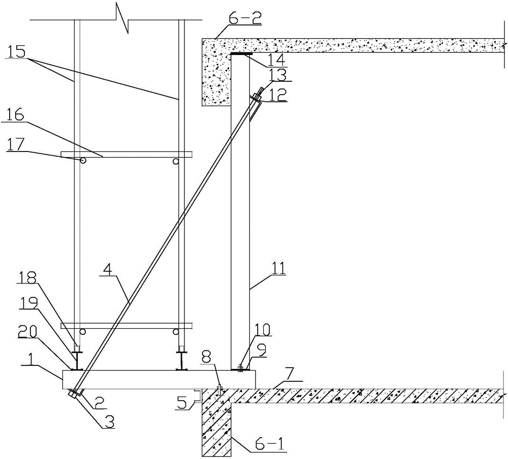
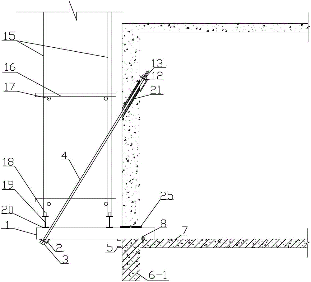
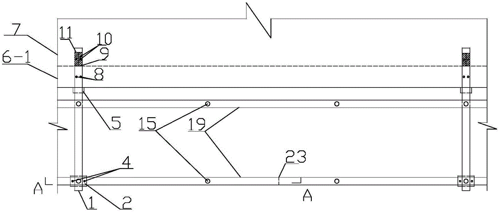
[0126] Such as Figure 1~4 Shown, self-stabilizing section steel suspension scaffold design and construction technology of the present invention:

[0127] 1. Construction drawing design of self-stabilizing steel suspension scaffolding:

[0128] See construction design for details Figure 1~4 ;

[0129] 2. Calculation of bearing capacity in cantilever state of main beam 1:

[0130] Before installing the steel bar 4, the main girder 1 is in a cantilever state, so the bearing capacity is calculated as follows:

[0131] 1. The maximum bending moment of cantilever main beam 1 is calculated according to the following formula:

[0132] In the formula: K 1 、K 2 - are the sub-item coefficients of live load and dead load respectively, taking 1.4 and 1.2 respectively;

[0133] q 1 ,q 2 —respectively, the construction live load and the dead load of the cantilever girder 1 g...


PUM

PropertyMeasurementUnit
Lengthaaaaaaaaaa
Thicknessaaaaaaaaaa
Lengthaaaaaaaaaa

Abstract

The invention belongs to the field of structural design and construction, and particularly relates to a design and construction technology of a self-stabilized section steel suspended scaffold. The design and construction technology mainly adopts the following steps that 1, the state bearing capacity of a main beam cantilever is calculated; 2, the bearing capacity of suspended system force bearing rod pieces is calculated; 3, a main beam is made; 4, a vertical beam is made; 5, secondary beams are made; 6, a rebar pulling rod is made; 7, the main beam is mounted; 8, the vertical beam is mounted; 9, the secondary beams are mounted; 10, the rebar pulling rod is mounted; and 11, the suspended system scaffold is built. Compared with a section steel cantilever scaffold, the design and construction technology of the self-stabilized section steel suspended scaffold is not provided with pre-buried lifting rings of steel wire ropes and anchoring rings of section steel supporting seats, and meanwhile, the nationwide key technical problems, caused by overturning force of a cantilever steel beam supporting seat, that a cast-in-place plate cracks and the front end of the cast-in-place plate is in torsional deformation are solved. Construction operation is easy; the construction period of the scaffold is shortened by a large margin; costs of section steel, pre-buried pieces and manpower are reduced in large quantities; significant economical and social benefits are achieved; and the requirements of efficiency, energy-saving and environment friendly construction are met.

Description

technical field [0001] The invention relates to a design and construction technology of a self-stabilizing steel suspension scaffold, which belongs to the cross field of structural design and construction technology. It is suitable for the construction of main scaffolds in structural forms such as shear walls, frames, frame-core tubes, and tube-in-tubes. The self-stabilizing steel suspension scaffold can be erected at a height of 50m at a time. Background technique [0002] At present, section steel cantilevered scaffolding is generally used in the construction of the main structure of high-rise buildings. However, the cable-stayed steel wire rope of the section steel cantilevered scaffold is extended under the load of the vertical pole, so that the anchor ring at the rear end of the section steel beam produces an overturning force, which leads to cracking of the cast-in-place slab and distortion of the front end due to eccentric force. Therefore, the "Safety Technical Spec...

Claims


Application Information

Patent Timeline
IPC IPC(8): E04G3/00E04G3/22
CPCE04G3/00E04G3/22
Inventor 贾华远蒲锰
Owner SHANDONG WANXIN CONSTR
Why Eureka
Try Eureka