Electric vehicle charging device

A technology for electric vehicles and charging devices, which is applied to electric vehicles, battery/fuel cell control devices, vehicle components, etc., can solve the problem of poor charging of battery packs, and achieve high charging reliability, good reliability and safety. high effect

Inactive Publication Date: 2019-11-08
CHINA JILIANG UNIV
View PDF5 Cites 0 Cited by
  • Summary
  • Abstract
  • Description
  • Claims
  • Application Information

AI Technical Summary

Problems solved by technology

As long as one single battery fails between the single batteries connected in series, the whole battery pack will not be charged well.

Method used


Image

  • Electric vehicle charging device
  • Electric vehicle charging device
  • Electric vehicle charging device

Examples


Embodiment 1

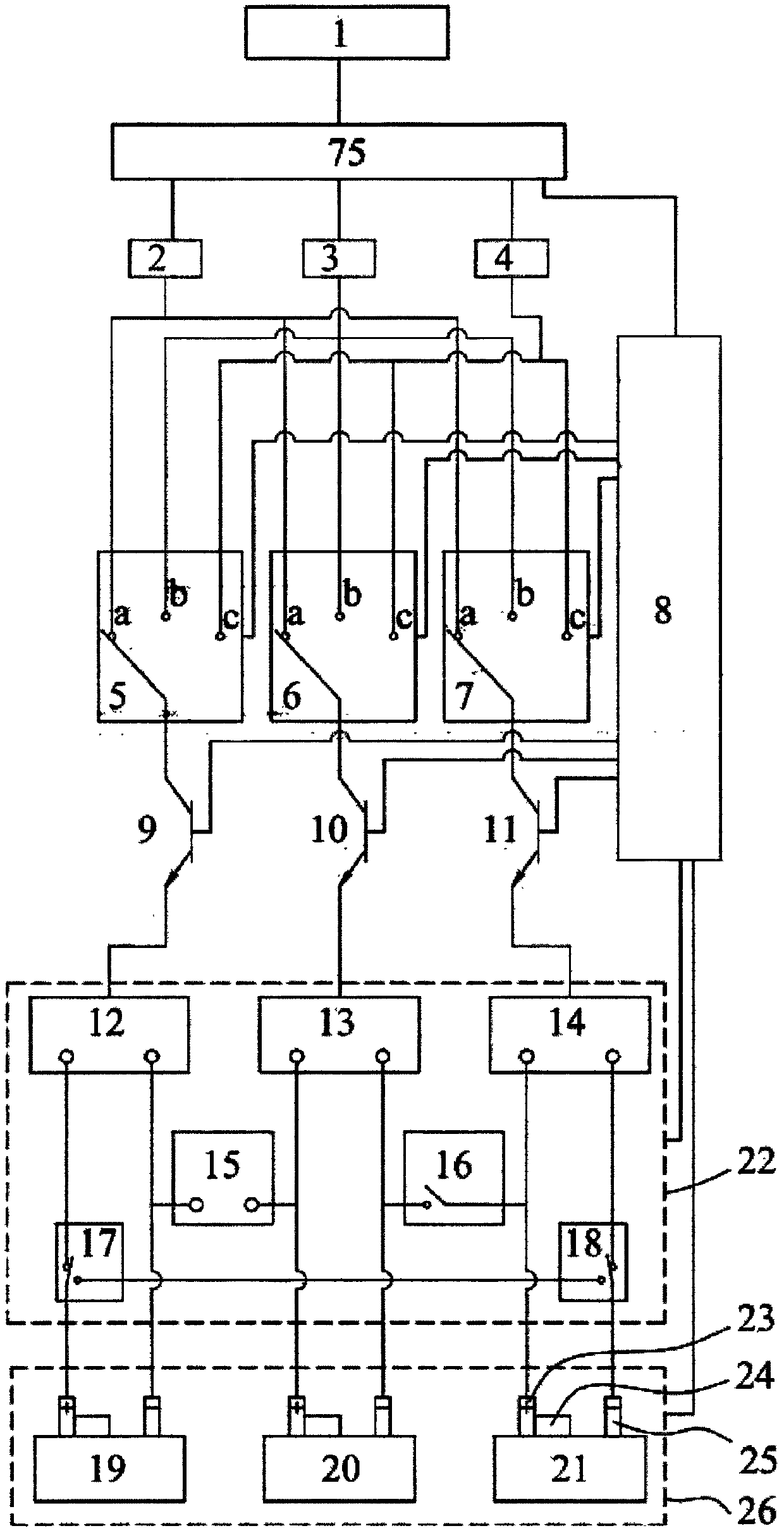
[0030] Embodiment 1, electric vehicle charging device, see figure 1 , Figure 7 As shown, the battery pack 26 of the electric vehicle is formed by serially connecting several mutually independent single cells; it includes a microcontroller 8 and a battery connection module 22, and also includes a charger and a switching switch which are respectively equal to the number of single cells. and a current limiting module; the battery connection module includes a body charging connection mechanism equal to the number of single batteries; each body charging connection mechanism is respectively provided with a body voltage detection chip 101; the power output terminals of each charger are connected one-to-one On one terminal of each switch selection terminal; the rotating end of each switch is connected one-to-one to one end of the current-limiting module, and the other end of each current-limiting module is one-to-one connected to the body of the battery connection module for charging...

Embodiment 2

[0052] Embodiment 2, the difference between embodiment 2 and embodiment 1 is that, see Figure 8 As shown, the temperature detection mechanism also includes No. 2 cooling extrusion spring 78, pressure sensor 76 and blocking block 77; On the left surface of the No. 2 temperature-lowering extrusion spring, the two ends are extruded respectively on the pressure sensor and the right end surface of the temperature-limiting insulating slider, and the pressure sensor is connected with the microcontroller.

[0053] Embodiment 2 reflects the temperature of the corresponding single battery through the pressure received by the pressure sensor. The greater the pressure received by the pressure sensor, the higher the temperature of the corresponding single battery, and the smaller the pressure received by the pressure sensor, the higher the temperature of the corresponding single battery. Low.

[0054] When the pressure detected by the pressure sensor is higher than the set value, that is...


PUM


Abstract

The present invention discloses an electric vehicle charging device and belongs to the electric vehicle charging technical field. With the electric vehicle charging device adopted, the damage of a single battery will not affect the charging of the other single batteries. The electric vehicle charging device comprises a micro controller, a battery connection module, chargers, change-over switches and current limiting modules; the number of the chargers, the number of the change-over switches and the number of the current limiting modules are equal to the number of the single batteries; the battery connection module includes bulk charging connection mechanisms of which the number is equal to the number of the single batteries; the power source output end of each charger is connected with one wiring end of the selection end of a corresponding change-over switch in a one-to-one corresponding manner; the rotating end of each change-over switch is connected with one end of a corresponding current limiting module in a one-to-one corresponding manner; the other end of each current limiting module is connected with a corresponding bulk charging connection mechanism of the battery connection module in a one-to-one corresponding manner; and the battery connection module is connected onto a battery pack.

Description

technical field [0001] The invention relates to the technical field of electric vehicle charging, in particular to an electric vehicle charging device. Background technique [0002] At present, electric vehicle charging devices all use a charger to charge the battery pack of the electric vehicle, and the single cells in the battery pack are connected in series with each other during the charging process. As long as one single battery fails among the single batteries connected in series, the whole battery pack will not be charged well. Therefore, it is very necessary to design a charging device for electric vehicles in which the damage of a single battery will not affect the charging of other battery cells. Contents of the invention [0003] The purpose of the present invention is to solve the above-mentioned shortcomings existing in the existing charging device for electric vehicles, and provide a charging device for electric vehicles. The electric vehicle charging devic...

Claims


Application Information

Patent Timeline
Patent Type & Authority Patents(China)
IPC IPC(8): B60L58/12B60L58/18
CPCB60L58/12B60L58/22Y02T10/70
Inventor 不公告发明人
Owner CHINA JILIANG UNIV
Why Eureka
Try Eureka