Method for measuring heat conductivity coefficient of conduction oil
A technology of thermal conductivity and measurement method, which is applied in the field of measurement of liquid thermal conductivity and thermal conductivity of heat conduction oil, can solve problems such as many solder joints, solder joints fall off, and decrease in measurement accuracy, and achieve wide temperature range and high accuracy. High, fixed effect
- Summary
- Abstract
- Description
- Claims
- Application Information
AI Technical Summary
Problems solved by technology
Method used
Image
Examples
Embodiment 1
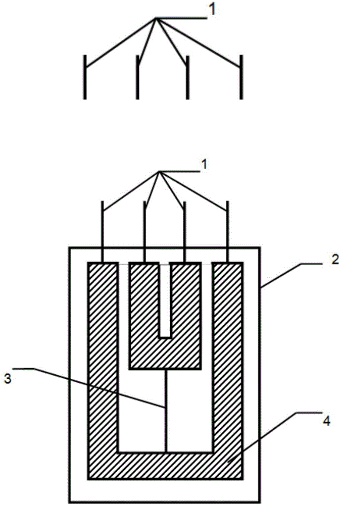
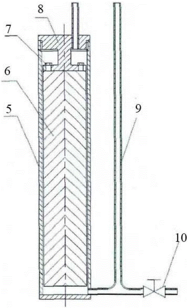
[0084] Using an integrated etching process, such as the method described in Example 1 of Chinese invention patent ZL 200310123131.0, replace the niobium sheet with a tantalum sheet, and obtain the following figure 1 The inverted double U-shaped heating wire structure, in the inverted double U-shaped structure, the width of the heating wire is 25μm, the length is 20mm, the lead-out wire is used as the wire and support structure of the middle heating wire, the width is 5mm, and the thickness is 30μm, and then added on the upper and lower surfaces After the polyimide membrane is placed on the attached figure 2 In the thermal conductivity cell where the thermal conductivity is measured as shown, connect other lines for measurement to form an attached image 3 As shown in the measuring device, you can start the measurement.
[0085] The measured results are shown in Table 1 below.
Embodiment 2
[0087] Using an integrated etching process, such as the method described in the embodiment of Chinese Invention Chinese Patent Application CN 104278274 A, does not require "sputtering on a glass substrate to form a molybdenum insulating layer, and then sputtering on the molybdenum insulating layer Copper to form a copper conductor body layer", sputtering copper directly on a glass substrate to form a copper conductor layer, and then obtained as attached figure 1 The inverted double U-shaped heating wire structure, in the inverted double U-shaped structure, the width of the heating wire is 25μm, the length is 20mm, the lead-out wire is used as the wire and support structure of the middle heating wire, the width is 5mm, the thickness is 1μm, and then added on the upper and lower surfaces After the polyimide membrane is placed on the attached figure 2 In the thermal conductivity cell where the thermal conductivity is measured as shown, connect other lines for measurement to form...
Embodiment 3
[0090] Use an integrated etching process, such as the method described in Example 1 of Chinese invention patent ZL 200910264387.0, change the palladium plating solution into platinum plating solution, and obtain the following figure 1 The inverted double U-shaped heating wire structure, in the inverted double U-shaped structure, the width of the heating wire is 25μm, the length is 20mm, the lead-out wire is used as the wire and support structure of the middle heating wire, the width is 5mm, and the thickness is 10μm, and then added on the upper and lower surfaces After the polyimide membrane is placed on the attached figure 2 In the thermal conductivity cell where the thermal conductivity is measured as shown, connect other lines for measurement to form an attached image 3 As shown in the measuring device, you can start the measurement.
[0091] The measured results are shown in Table 1 below.
PUM
| Property | Measurement | Unit |
|---|---|---|
| Width | aaaaa | aaaaa |
| Length | aaaaa | aaaaa |
| Width | aaaaa | aaaaa |
Abstract
Description
Claims
Application Information
 - R&D
- Intellectual Property
- Life Sciences
- Materials
- Tech Scout
- Unparalleled Data Quality
- Higher Quality Content
- 60% Fewer Hallucinations
Browse by: Latest US Patents, China's latest patents, Technical Efficacy Thesaurus, Application Domain, Technology Topic, Popular Technical Reports.
© 2025 PatSnap. All rights reserved.Legal|Privacy policy|Modern Slavery Act Transparency Statement|Sitemap|About US| Contact US: help@patsnap.com


