Rotor-spinning method for spinning of high-strength yarns
A technology of rotor spinning and rotor spinning, which is applied to spinning machines, open-end spinning machines, and continuous winding spinning machines, etc. It can solve problems such as poor fiber arrangement, entanglement, and reduced strength, and achieve High fiber straightness, high yarn quality and good shape
- Summary
- Abstract
- Description
- Claims
- Application Information
AI Technical Summary
Problems solved by technology
Method used
Image
Examples
Embodiment 1
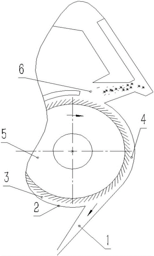
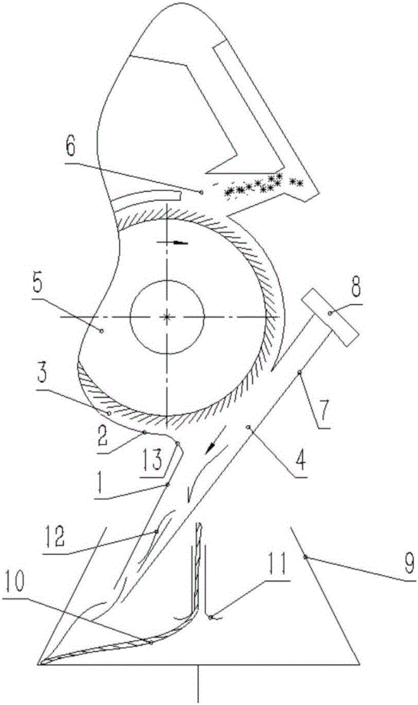
[0032] A rotor spinning method for spinning high-strength yarn. The high-strength yarn is spun through a spinning process. In the spinning process, a rotor spinning device that eliminates eddy currents is used, and single fibers 12 enter to eliminate eddy currents. In the rotor 9 of the rotor spinning device, the yarn 10 is spun through the false twist disc 11. The structure of the rotor spinning device is as follows: figure 2 As shown, the rotor spinning device includes a vortex elimination channel 4, and the vortex elimination channel includes a fiber delivery channel 1 and a bypass channel communicated with the air supply pump 8; the bypass channel and the central axis of the fiber delivery channel are on the same straight line, and The bypass channel 7 is located in the opposite direction of the fiber feeding direction in the fiber feeding channel 1; the fiber feeding channel entrance of the fiber feeding channel and the bypass channel is opened on one side of the vortex e...
Embodiment 2
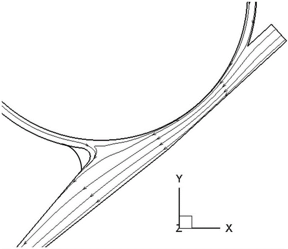
[0035] A rotor spinning method for spinning high-strength yarn. The high-strength yarn is spun through a spinning process. In the spinning process, a rotor spinning device that eliminates eddy currents is used, and single fibers 12 enter to eliminate eddy currents. In the rotor 9 of the rotor spinning device, the yarn 10 is spun through the false twist disc 11. The rotor spinning device includes the vortex elimination channel 4, and the vortex elimination channel includes the fiber delivery channel 1 and the air supply pump 8 A connected bypass channel; the central axis of the bypass channel and the fiber transmission channel is on the same straight line, and the bypass channel 7 is located in the opposite direction of the fiber transmission direction in the fiber transmission channel 1; there is a split fiber transmission channel on one side of the vortex elimination channel and the fiber feeding passage entrance of the bypass passage, the eddy current elimination passage is c...
Embodiment 3
[0038] A rotor spinning method for spinning high-strength yarn. The high-strength yarn is spun through a spinning process. In the spinning process, a rotor spinning device that eliminates eddy currents is used, and single fibers 12 enter to eliminate eddy currents. In the rotor 9 of the rotor spinning device, the yarn 10 is spun through the false twist disc 11. The rotor spinning device includes the vortex elimination channel 4, and the vortex elimination channel includes the fiber delivery channel 1 and the air supply pump 8 A connected bypass channel; the central axis of the bypass channel and the fiber transmission channel is on the same straight line, and the bypass channel 7 is located in the opposite direction of the fiber transmission direction in the fiber transmission channel 1; there is a split fiber transmission channel on one side of the vortex elimination channel and the fiber feeding passage entrance of the bypass passage, the eddy current elimination passage is c...
PUM
| Property | Measurement | Unit |
|---|---|---|
| length | aaaaa | aaaaa |
| diameter | aaaaa | aaaaa |
Abstract
Description
Claims
Application Information
 - R&D
- Intellectual Property
- Life Sciences
- Materials
- Tech Scout
- Unparalleled Data Quality
- Higher Quality Content
- 60% Fewer Hallucinations
Browse by: Latest US Patents, China's latest patents, Technical Efficacy Thesaurus, Application Domain, Technology Topic, Popular Technical Reports.
© 2025 PatSnap. All rights reserved.Legal|Privacy policy|Modern Slavery Act Transparency Statement|Sitemap|About US| Contact US: help@patsnap.com


