A pneumatic brake control mechanism for braking energy feedback

A technology of pneumatic brake and control mechanism, which is applied in the direction of electric brake system, electric vehicle, operation mode, etc. It can solve the problems that electric vehicles cannot give full play to the feedback of braking energy, affect the mileage and reliability of electric vehicles, etc. To achieve the effect of optimal control

Inactive Publication Date: 2020-09-08
QINGDAO UNIV
View PDF6 Cites 0 Cited by
  • Summary
  • Abstract
  • Description
  • Claims
  • Application Information

AI Technical Summary

Problems solved by technology

[0003] The purpose of the present invention is to provide a new type of brake energy feedback pneumatic brake operating mechanism and related control algorithm, which has the condition that the total braking torque of the electric vehicle maintains a stable corresponding relationship with the brake pedal stroke and pedal force Under this condition, it can automatically adjust and distribute the braking torque ratio of the electric braking and mechanical braking systems, and adjust the electric braking power in real time when the driving state of the electric vehicle is constantly changing, so as to maximize the ability of electric braking and save battery power. , the advantage of prolonging the mileage of driving, solves the problem that the braking torque of electric braking is controlled in a small range, causing electric vehicles to not fully exert the efficiency of braking energy feedback, and affecting the driving mileage and reliability of electric vehicles

Method used


Image

  • A pneumatic brake control mechanism for braking energy feedback

Examples


Embodiment Construction

[0010] The following will clearly and completely describe the technical solutions in the embodiments of the present invention with reference to the accompanying drawings in the embodiments of the present invention. Obviously, the described embodiments are only some, not all, embodiments of the present invention. Based on the embodiments of the present invention, all other embodiments obtained by persons of ordinary skill in the art without making creative efforts belong to the protection scope of the present invention.

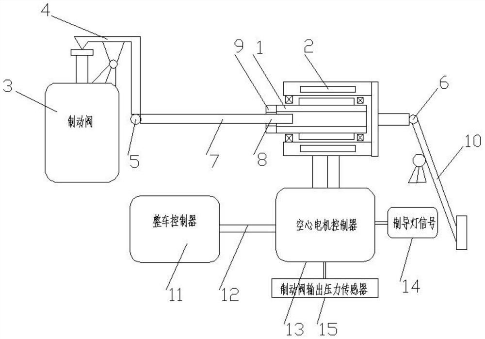
[0011] see figure 1 , the present invention provides a technical solution: an air brake operating mechanism for braking energy feedback, including a hollow rotor 1 and a hollow motor controller 13, the motor assembly is connected in series to the braking system of a traditional air brake system. In the valve control rod 7, the hollow rotor 1 is a hollow structure, and one end of the hollow rotor 1 is connected to a nut 9, the brake valve control rod 7 is disco...


PUM


Abstract

The invention discloses an air pressure braking manipulating mechanism used for braking energy feedback. The air pressure braking manipulating mechanism used for braking energy feedback comprises a hollow rotor and a hollow motor controller; a motor assembly is connected into a braking valve manipulating pull rod of a traditional air pressure braking system in series; the hollow rotor is of a hollow structure, and one end of the hollow rotor is connected with a nut; the braking valve manipulating pull rod is disconnected from a proper position; one end is machined into a threaded rod and is connected with the nut, and the other end is connected with a stator shell; one end of the braking valve manipulating pull rod is connected with a rocker arm of a braking valve through a hinged structure B or other pull rods; the rocker arm is connected with the braking valve; and the other end of the braking valve manipulating pull rod is connected with a braking pedal through a hinged structure D or other transmission mechanisms. The air pressure braking manipulating mechanism used for braking energy feedback solves the problems that the braking torque of electric power braking is controlled within a small range, it is caused that an electric automobile cannot fully play the braking energy feedback effect, and the driving mileage and reliability of the electric automobile are affected, the electric energy of a storage battery can be saved, and the driving mileage is prolonged.

Description

technical field [0001] The invention relates to the technical field of brake manipulation, in particular to an air pressure brake manipulation mechanism for braking energy feedback. Background technique [0002] All electric vehicles have a braking energy feedback function, which controls the driving motor as a generator to generate braking resistance torque to achieve vehicle braking. Braking energy feedback can effectively recover vehicle kinetic energy, convert it into electric energy, and reuse it for vehicle driving power, which can effectively improve the driving range of electric vehicles. It can also reduce the wear of the mechanical vibration system and prolong the service life of the mechanical braking system. Therefore, when electric vehicles are braking, electric braking should be used as much as possible. However, due to the influence of electric braking in actual working conditions, it is impossible to provide and mechanical braking due to the influence of fac...

Claims


Application Information

Patent Timeline
Patent Type & Authority Patents(China)
IPC IPC(8): B60L7/26
CPCB60L7/26B60L2260/44
Inventor 尹怀仙张翼霍炜郑莉莉樊华敏黄福闯
Owner QINGDAO UNIV
Why Eureka
Try Eureka