Pivotal device

A technology of hubs and connectors, applied in the field of hubs, can solve problems such as the inability of hubs to achieve functions

Inactive Publication Date: 2010-10-27
KANGZHUN ELECTRONICS TECH KUNSHAN +1
View PDF0 Cites 4 Cited by
  • Summary
  • Abstract
  • Description
  • Claims
  • Application Information

AI Technical Summary

Problems solved by technology

Existing hubs cannot achieve the above functions

Method used


Image

  • Pivotal device
  • Pivotal device
  • Pivotal device

Examples


Embodiment Construction

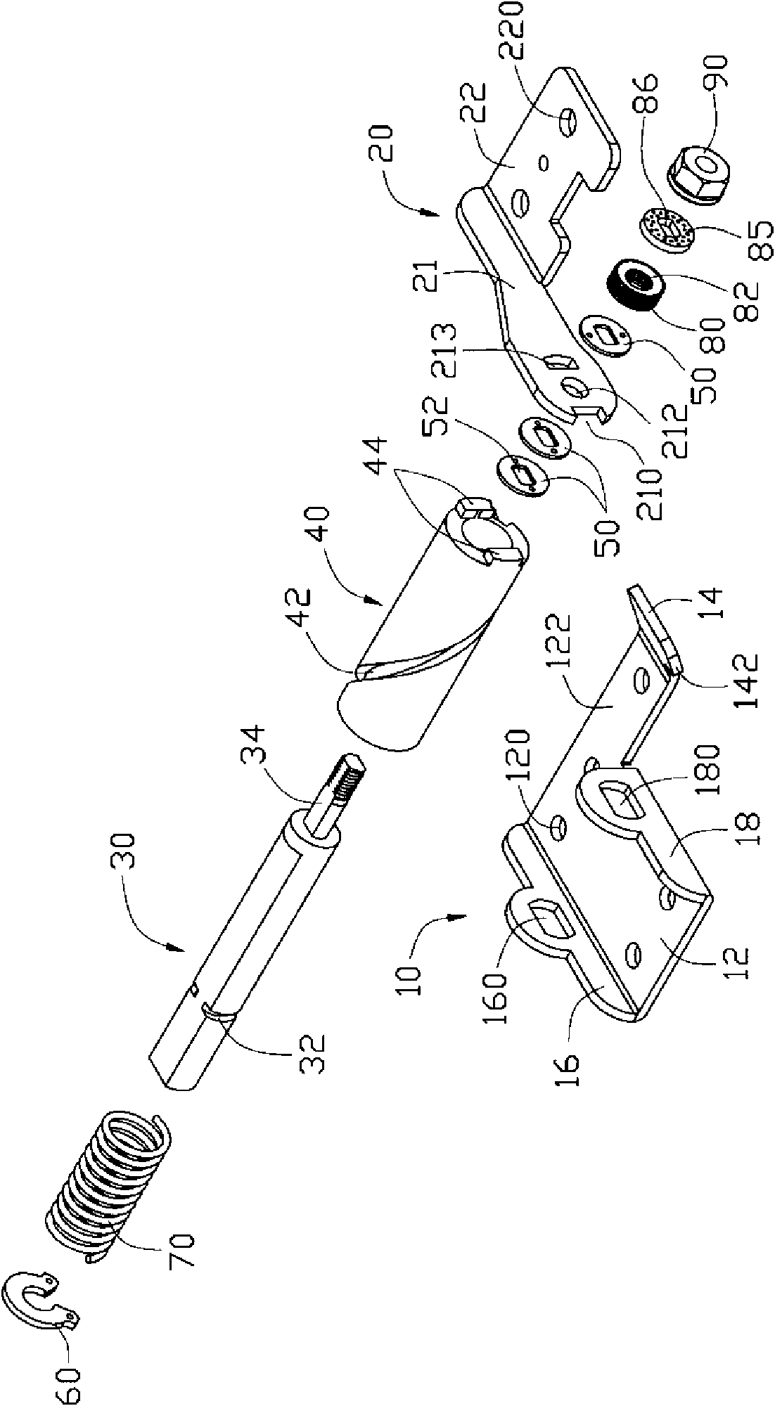
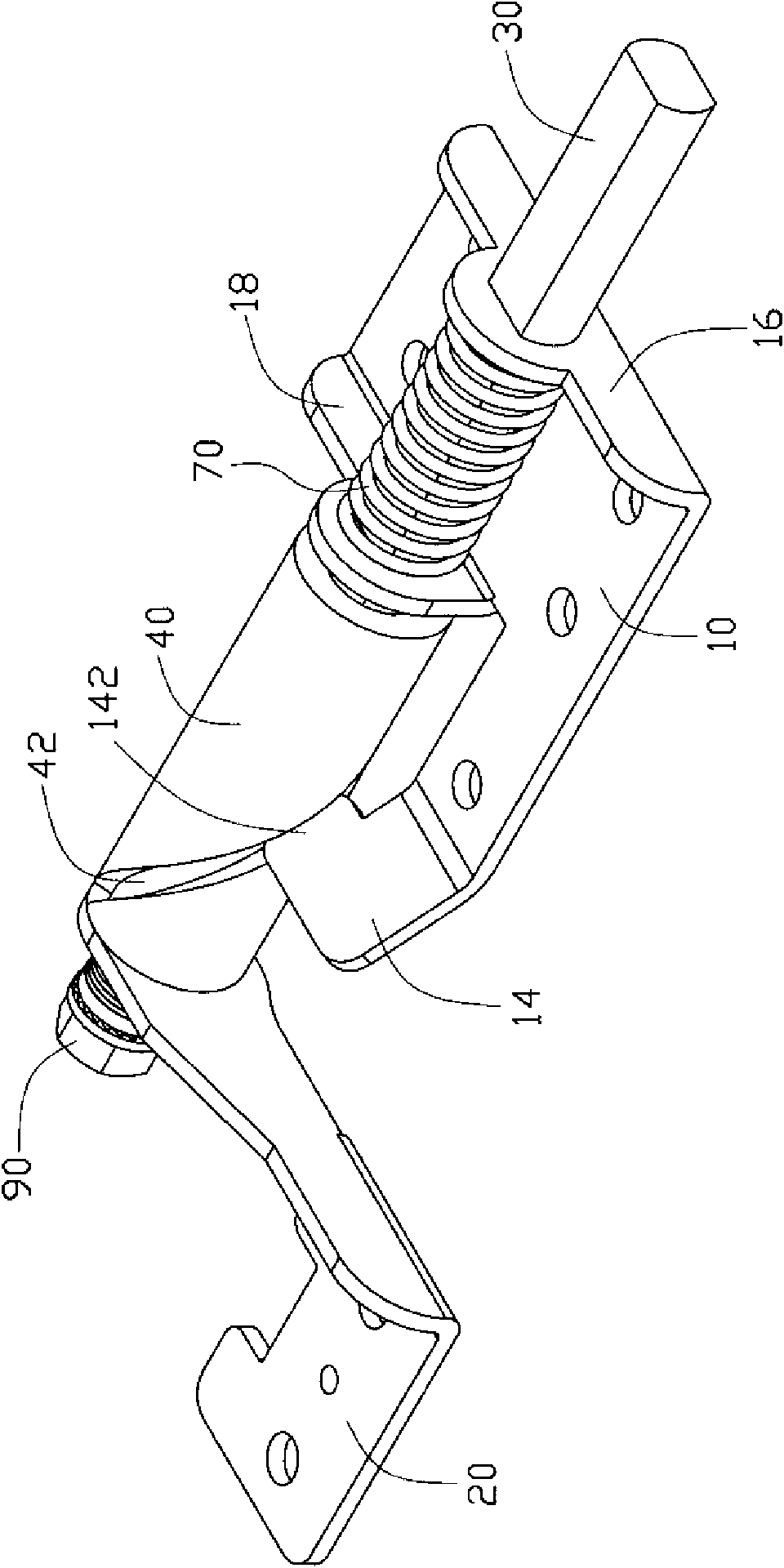
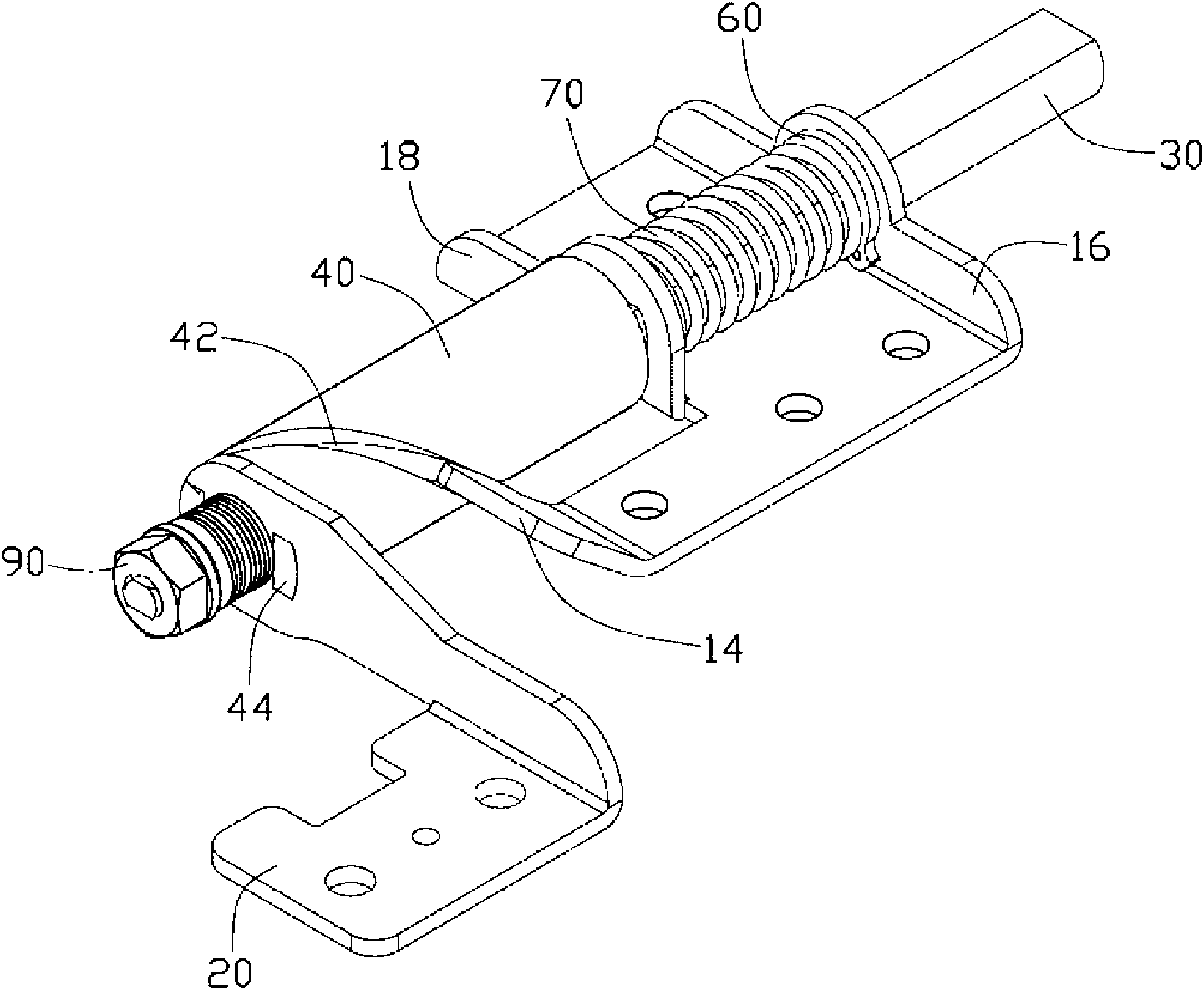
[0012] Please refer to figure 1 A preferred embodiment of the hinge of the present invention includes a first connecting piece 10, a second connecting piece 20, a shaft 30, a sleeve 40, several friction plates 50, and a substantially "C" shaped snap ring 60 . An elastic member 70 , an elastic sheet group 80 including several elastic washers, a washer 85 and a fixing member 90 . In this embodiment, the elastic member 70 is a spring. The first connecting member 10 and the second connecting member 20 are respectively used to be fixed on two components that need to rotate with each other, such as the upper cover and the base of the electronic device.

[0013] The first connecting member 10 includes a fixing plate 12 . The fixing plate 12 is provided with a plurality of fixing holes 120 for passing through screws or rivets so as to fix the first connecting member 10 to the base of the electronic device. One side of the fixing plate 12 extends vertically upward to form a first co...


PUM


Abstract

The invention discloses a hinge device, comprising a first connecting piece, a second connecting piece, a shaft rod and a fixation component, wherein, one end of the shaft rod is provided with a fixation part which can be rotatablely assembled in the second connecting piece; the fixation component is fixed at the tail end of the fixation part; and the first connecting piece protruded with a clamp block; and the first connecting piece can be axially and movably connected with the shaft rod. The hinge device also comprises a sleeve fixed on the second connecting piece; a helical chute is arranged on the sleeve; the clamp block is slidably clamped on the chute; and when the second connecting piece is rotated, the clamp block pushes the sleeve, thereby driving the second connecting piece and the shaft rod to go away from the first connecting piece in an axial direction, so as to realize axial movement of the hinge device.

Description

technical field [0001] The invention relates to a hinge device. Background technique [0002] Portable electronic devices such as notebook computers and mobile phones often adopt a foldable structure to save space. Generally, the upper cover and the base of these electronic devices are connected by a hinge, so that the upper cover can be opened and closed relative to the base. When not in use, the upper cover and the base can be folded up relative to each other. [0003] The hinge generally includes two connecting parts respectively fixed to the upper cover and the base of the electronic device, and the two connecting parts are pivotably connected by a shaft so that the upper cover can rotate relative to the base. However, when the electronic device is in use, sometimes the upper cover needs to be moved laterally relative to the base so that the upper cover and the base intersect. Existing hubs cannot realize the above functions. Contents of the invention [0004] In v...

Claims


Application Information

Patent Timeline
Patent Type & Authority Applications(China)
IPC IPC(8): F16C11/04F16C11/10H05K7/16H04M1/02G06F1/16
Inventor 江振伟
Owner KANGZHUN ELECTRONICS TECH KUNSHAN
Why Eureka
Try Eureka