Al technical title is built by PatSnap Al team. It summarizes the technical point description of the patent document.
A technology of vertical milling machine and main transmission, which is applied in the direction of driving device, metal processing machinery parts, maintenance and safety accessories, etc. It can solve the problems of fast gear wear, narrow speed regulation range, single model of machine parts, etc., and achieve good lubrication effect , the effect of wide speed range
Active Publication Date: 2012-10-10
SHANDONG YOURONG MACHINE TOOL
View PDF8 Cites 4 Cited by
Summary
Abstract
Description
Claims
Application Information
AI Technical Summary
This helps you quickly interpret patents by identifying the three key elements:
Problems solved by technology
Method used
Benefits of technology
Problems solved by technology
[0002] In the existing vertical milling machine, the main drive is changed through the gear, so that the main shaft can obtain 12 different speeds of 45-1300 r / min, the speed regulation range is narrow, the machined parts are of a single model, the main shaft is fixed, and only the control work is required. The table moves up, down, left, and right to process the object. The axis of the spindle cannot achieve axial feed, and the processing range of the milling machine is small.
In addition, the lubrication in the main transmission box is only through the splash lubrication of the oil throwing pan, the gears and bearings are not sufficiently lubricated, the gears wear quickly, the bearings are easy to burn rings, and the lubrication effect is poor
Method used
Image
Click on the blue label to locate the original text in one second.
Reading with bidirectional positioning of images and text.
Examples
Embodiment Construction
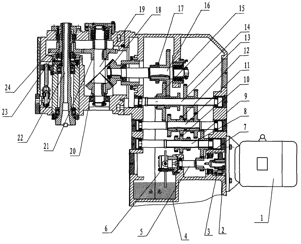
[0010] The present invention will be further described below in conjunction with accompanying drawing and specific embodiment:
[0011] A vertical milling machine main transmission device, such as figure 1 As shown, it includes: main motor 1, transmission box 2, elastic coupling 3, oil pool 4; the oil pool 4 is designed in the transmission box 2, and a transmission shaft 5 is installed in the transmission box 2, and the main motor 1 passes through the elastic Coupling 3 links to each other with transmission first shaft 5 in transmission case 2, and one end of transmission first shaft 5 is fixedly equipped with cycloid pump 6, and a shaft gear 7 is designed on transmission first shaft 5; Two transmission shafts 8, two transmission shafts 8 are designed with two shaft gears 9, one shaft gear 7 and two shaft gears 9 are meshed for transmission, three transmission gears 10 are fixedly installed on the two transmission shafts 8, and the transmission box 2 is designed with The tran...
PUM
Abstract
The invention discloses a main driving device for a vertical milling machine, which has wide speed regulation range and can achieve axial feeding and good lubrication effect, wherein the main driving device comprises a main motor, a drive housing, an elastic coupler, an oil basin, a first transmission shaft, a cycloid pump, a second transmission shaft, a second shaft gear, a triple gear, a third transmission shaft, a change gear, a fourth transmission shaft, a duplicate gear, a change gear, a fifth transmission shaft, a change gear, a bevel gear and a vertical shaft; a first shaft gear is arranged on the first transmission shaft; the bevel gear is arranged at one end of the vertical shaft; a skew gear is arranged at the other end of the vertical shaft; a main shaft is arranged on one side of the vertical shaft; and a spline housing and the skew gear are arranged on the outer side of the main shaft. The main driving device has the advantages as follows: the main shaft can obtain 12-level rotational speed within 35 to 1500 rpm (Revolutions Per Minute) through a 3*2*2 structural formula, and the speed regulation range is wide; the main shaft and the spline housing are connected through a spline, and the main shaft can move upwards and downwards in the spline housing in the axial direction; in addition, the cycloid pump is installed at one end of the first transmission shaft, lubricant in the oil basin in the drive housing can be conveyed to lubricating points on the gears and bearings through an oil line with the help of the power of the first transmission shaft, and the lubrication effect is good.
Description
technical field [0001] The invention relates to a milling machine main transmission system, in particular to a vertical milling machine transmission device. Background technique [0002] In the existing vertical milling machine, the main drive is changed through the gear, so that the main shaft can obtain 12 different speeds of 45-1300 r / min, the speed regulation range is narrow, the machined parts are of a single model, the main shaft is fixed, and only the control work is required. The table moves up, down, left, and right to process objects. The axial direction of the spindle cannot achieve axial feed, and the processing range of the milling machine is small. And the lubrication in the main transmission box is only through the splash lubrication of the oil throwing pan, the gears and bearings are not sufficiently lubricated, the gears wear quickly, the bearings are easy to burn rings, and the lubrication effect is poor. Contents of the invention [0003] The purpose of...
Claims
Application Information
Patent Timeline
Application Date:The date an application was filed.
Publication Date:The date a patent or application was officially published.
First Publication Date:The earliest publication date of a patent with the same application number.
Issue Date:Publication date of the patent grant document.
PCT Entry Date:The Entry date of PCT National Phase.
Estimated Expiry Date:The statutory expiry date of a patent right according to the Patent Law, and it is the longest term of protection that the patent right can achieve without the termination of the patent right due to other reasons(Term extension factor has been taken into account ).
Invalid Date:Actual expiry date is based on effective date or publication date of legal transaction data of invalid patent.