
Distributed network-based scene surveillance radar redundancy control system

A surface surveillance radar, distributed network technology, applied in general control systems, control/regulation systems, comprehensive factory control, etc., can solve the problems of relying on the reliability of the arbitration system, the system cannot work normally, and the loss of radar data, etc., to achieve flexibility. Redundant switching control strategy, strong scalability, good reliability

Active Publication Date: 2017-04-05
CHINA ELECTRONIC TECH GRP CORP NO 38 RES INST
View PDF3 Cites 5 Cited by
  • Summary
  • Abstract
  • Description
  • Claims
  • Application Information

AI Technical Summary

Problems solved by technology

For surface surveillance radar, such a system has two shortcomings. One is that it relies too much on the reliability of the arbitration system. All work is done through the arbitration system, and the arbitration system is unique. If it fails, the entire system will unable to work properly
The second is that the antenna of the surface surveillance radar rotates at a relatively fast speed, about one revolution per second. In order to ensure the continuity of the surveillance target, the switching action should be completed within one second, and this kind of switching relying on the system arbitration system needs to go through several steps. It will take a certain amount of time to finally complete the switch, and some radar data will be lost

Method used


Image

  • Distributed network-based scene surveillance radar redundancy control system
  • Distributed network-based scene surveillance radar redundancy control system
  • Distributed network-based scene surveillance radar redundancy control system

Examples


Embodiment Construction

[0025] In order to make the objectives, technical solutions and advantages of the present invention more clear, the present invention will be further described in detail below in conjunction with implementation examples. It should be understood that the specific embodiments described here are only used to explain the present invention, not to limit the present invention.

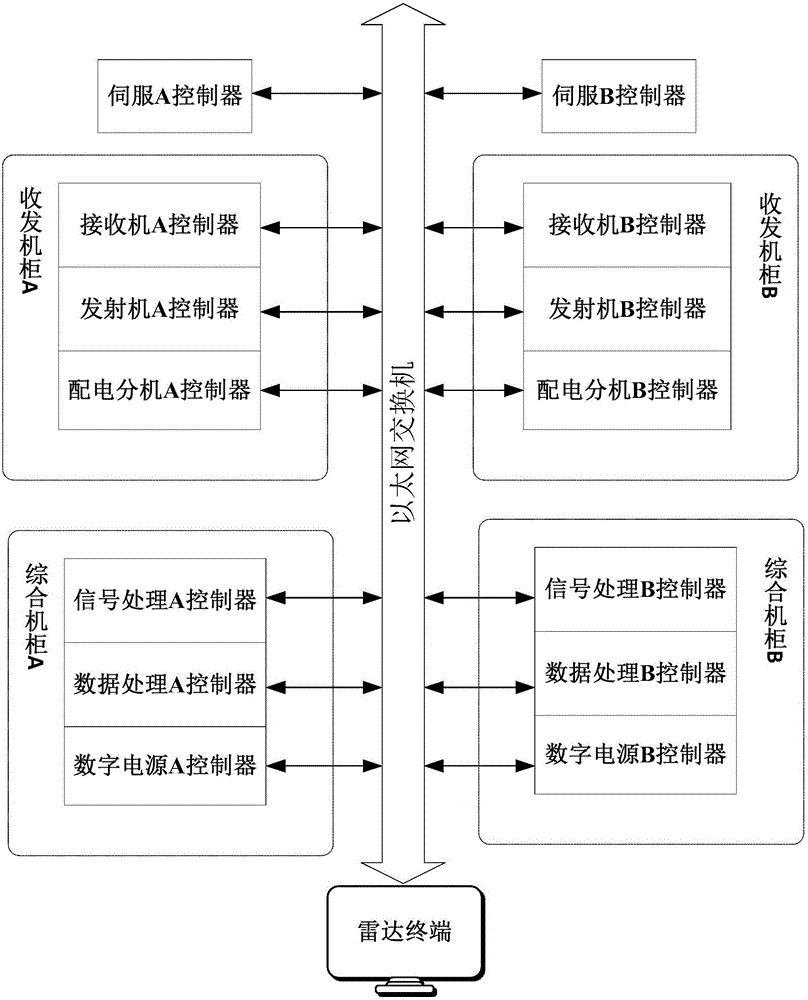
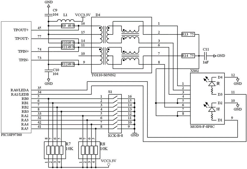
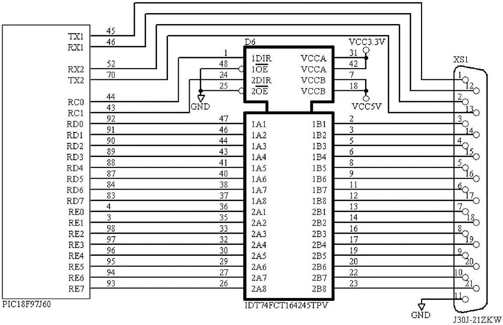
[0026] Such as figure 1 Shown is a schematic structural diagram of the distributed network-based surface surveillance radar redundant control system of the present invention. The distributed network-based surface surveillance radar redundant control system is provided with radar components, Ethernet switches, radar terminals, and radar terminals. Radar components include servo controllers, transmitter controllers, receiver controllers, power distribution extension controllers, signal processing controllers, data processing controllers, and digital power controllers that form each distributed network node, al...


PUM


Abstract

A distributed network-based scene surveillance radar redundancy control system disclosed by the present invention is equipped with a radar assembly, an Ethernet switch and a radar terminal. In order to enable the radar assembly to purposively and respectively select one of two servo controllers, one of two transmitter controllers, one of two receiver controllers, one of two distribution extension controllers, one of two signal processing controllers, one of two data processing controllers and one of two digital power supply controllers which have different types to from a main body frame, all controllers and the radar terminal are connected with the Ethernet switch as the nodes of the distributed network and are controlled by the distributed node control units respectively, thereby forming the distributed network. The distributed network adopts the distributed network topology structures as the star structures, and in the distributed network, the priority of the radar terminal is highest. The distributed network-based scene surveillance radar redundancy control system of the present invention has the characteristics of being simple and reliable, and being strong in extensible capability and flexible in redundancy switching control mode.

Description

technical field [0001] The invention relates to a redundant switch and control system in the field of radar control, in particular to a distributed network-based surface surveillance radar redundant control system. Background technique [0002] Airport Surface Surveillance Radar (SMR) is an independent non-cooperative monitoring equipment, which is an important part of air traffic control facilities. It uses primary radar detection technology to monitor airport surface targets. The radar does not monitor airport surface targets. It needs the cooperation of the monitored target, its working performance is not affected by external light, and has the ability to monitor around the clock; relying on the ability of electromagnetic waves to penetrate clouds, rain, fog and other media, it has the ability to monitor around the clock. Based on the above characteristics, the surface surveillance radar adopts a dual-radar redundant system architecture to improve the mission reliability ...

Claims


Application Information

Patent Timeline
Patent Type & Authority Applications(China)
IPC IPC(8): H04L29/08G05B19/418G05B9/03
CPCY02P90/02H04L67/10G05B9/03G05B19/4185
Inventor 邵威刘健杨志谦郭立俊李辉
Owner CHINA ELECTRONIC TECH GRP CORP NO 38 RES INST
Learn More